Be careful here. The TP4056 modules are disigned for USB 5V charging, if you want to use them as a solar charger then you need to check that the open circuit voltage of the solar panel (i.e. when the battery is fully charged) does not exceed the absolute max input voltage of the TP4056, 8V.
The last thing you want connected to a LiPo is a fried charger circuit …
I agree with all of your points here. The TP4056 does work for my specific use case though (I’ve been running a node with it for over a year). A typical lora node needs so little power that there can be huge inefficiencies in the charging of the lipo cell since there will still be more than enough for the node itself. I know that the TP4056 is not a MPTT, but it works well with a 6V solar panel from Aliexpress.
This allows me to build nodes for a total of 8 bucks which is pretty amazing. All my circuitry is in fire proof boxes and even if a lipo would explode at some point, it would be contained.
I think I will design a different board with a LiFePo4 cell at some point, but for now LiPo works and if you oversize the power input a little bit this will be a good and sustainable node.
For example my node has been running for a year now and has never even gone below 3.9V. At this point I am more concerned about making the battery life shorter because it is not good for LiPo to stay at high voltage all the time.
On that note I am still very much open on suggestions on what to replace the TP4056 with. I have not found a good all in one solution replacement for it.
If you want to use the TP4056 modules for solar charging, then the solution is simple enough, put a low drop out 5V regulator, such as MCP1702, between the solar panel and the TP4056.
What was the open circuit voltage, in bright sunlight, of the solar panels you are using ?
Can you tell us which fireproof box you are using ?
It may be useful to include some mounting holes in the PCB. I generally use a 3.0 mm or 3.2 mm hole in each corner and fit a plastic standoff to mount the PCB. This is obviously not needed if you have in mind another mounting arrangement.
For LiPo charging I have been using CN3065 breakouts. So far so good. I just need to make sure my panels don’t output too high a voltage when unloaded.
Missing from your schematic is a circuit to measure battery voltage, unless I missed it. As far as I’ve seen your options are a 100KOhm divider with a fet and 2nd I/O pin to turn it on/off or a 1M-4.7MOhm divider with a cap to allow stable readings. I use the latter successfully on STM32L0 boards (2x4.7M divider with 100nF cap).
In terms of low-voltage cut-off, I use the voltage divider and put the node into permanent sleep when it reaches 3.1v. Very little runtime left below that anyway. It takes some fiddling to get all the settings and I/O pins right to achieve the lowest consumption in sleep mode, so expect some experimentation and frustration! A single I/O pin in the wrong state can easily 10x your consumption when you’re in the single digit uA range. I would view any low-voltage cut-off in the regulator or charger as a second-level safety so wouldn’t worry about the exact voltage.
If you want the regulator with the lowest quiescent current, the TPS782 is down to 500nA. Only matters if you are really getting into single digit uA sleep. I would add a 4.7uF-10uF cap on the LDO output, btw, that radio takes a big drink when the TX turns on…
Something else I do on my low-power boards is to add a jumper on gnd where I want to measure current. This way I can add a shunt (uCurrent Gold in my case) to tune the sleep modes. I put it into gnd so the scope gnd, which you have to connect to one side of the shunt, is device gnd allowing me to hook probes to other pins to trigger the scope and show status/phases of the app.
@LoRaTracker you keep mentioning LiFePo4, can you provide some links to the actual batteries you use? I use small flat LiPo in the 200mAh-400mAh range, which fit wonderfully on the back of the tiny boards I use. I’ve looked into LiFePo4 over the years and the only smallish ones are 10440 cells (“AAA” size) which, with holder, add considerable bulk and cost as much as a small LiPo that is 2x-3x the capacity or as much as an 18650 cell (larger) that has 10x the capacity. Are 10440 cells what you use? Have you found a brand that is reliable?
NB: I’m not disputing the benefits of LiFePO4, I just haven’t found a compelling form-factor/capacity(/price) that would make me switch…
I have been using a Soshine AA LiFePO4, 700mAhr. They weigh in at 17.41g, which is the same weight as a LiPo of the same capacity.
To me, the safety issue is very important, I dont want trackers and things to catch fire,abuse in use is likely, so I avoid LiPos.
I would use LiPos if you built into a project an automated shut down system, in addition to the LIpos own protection circuit, but that adds extra components and size too.
One thought to consider, if you were selling your product to the general public, would you consider a design based on a LiPo\TP4056 adequate and what would your insurers think ?
I guess your PCB will probably work, i do have some tips.
Aside for the details of this specific design, i always add :
Mounting holes. 3 mm, with the copper cleared form the holes.
A version number on the silk screen and top and bottom copper. I start usually with 0.1.
A date.
A URL and logo.
Specifically for this design :
Consider adding a ground plane.
The antenna connector should be a close as possible to the radio module. I’d make the PCB a bit longer and move the connector to the center of the PCB edge. The trace should be as short as possible and the ground plane or wide traces are just as important as the antenna traces.
Most of the texts are going to be under the arduino mini. Can you move them ?
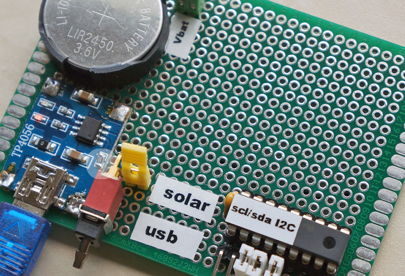
true… the first chip I mentioned is 'true mppt and the cn3065 board from the picture is a cheap managed charger with build in protection, better and safer then the TP4056 but, if you live in a country with few sunhours and a lot of fluctuation choose a mppt charger.
* i’ve tested that little red module with an 750 mA lipo and solarpanel connected that worked well
old experiment… charging a LIR2450 solar/usb with an adapted TP4056 module
The idea of powering unattended Lorawan sensors with MPPT is interesting, as it could probably reduce the required size of the solar panel, and the SPV1040 seems the good IC to fit the purpose! Unfortunately the only boards that I can find with this IC are expensive developer boards by ST, so unless we find someone that wants to engage with the challenge , we would probably have to wait to check on this…
Thanks a lot for all your great input here! This seems like a really active and productive community.
I think a battery voltage sensor circuit would be a great addition. I have never build something like that (in code or in hardware), so if you could give me some pointers on how to design one for a lipo battery it would be great!
EDIT: Also it was mentioned that I should put a MCP1702 between the solar panel and the TP4056. Would that really improve things? I mean I could do that since I use the same chip on the output side already. I am just not sure if it would help that much.
@5774430de7caf50f006f, the RFM doesn’t really need a pi-network, and I think the OP probably doesn’t have the equipment to measure the parameter values needed to calculate the values of the pi-network components anyway. If you keep the RF-trace short and use a proper antenna, it will work like a charm.
However, what I would do is move the location for the edge SMA connector a lot closer to the RFM, and put that soldering hole for a wire or helical antenna in the center pad of the SMA-connector footprint. Shortens the RF-trace and saves space too.
And also IMPORTANT! Connect the GND-pin of the RFM right next to the RF-output pin to the GND-plane. It looks like it is unconnected…
 , we would probably have to wait to check on this…