@Algram There is a nice and simple way to measure the battery voltage which does not waste power. The method uses the fact that the digital outputs of the processor for a logical 1 go up practically to almost the Vcc voltage.
So what you do: you assign one digital output. You connect a resistor bridge that brings the voltage down to -say- one 1/4th (if your battery is 3.6V), and the output of that resistor bridge is connected to an analogue input, where you use the ADC to sample the voltage using the internal 1.1 Volt reference (!) as reference. Voila! Important is that the resistor bridge brings the battery voltage below the 1.1 Volt reference of course.
In your sketch you set the digital output to 1 when you want to do a measurement, you do one AD-conversion (or several, if you’d like to average), and then you set the digital output back to 0, so the circuit uses zero power when you are not measuring.
In our devices, we actually measure the battery voltage when the RFM is transmitting, because that is the maximum stress for the battery. So we send the TX-opcode to the RFM, wait for the RFM to start transmitting (typically takes several milliseconds), and then sample the battery voltage.
Hope this helps! If you implement this idea, you may donate me one can of Coca Cola Zero
The TPLs are handy in some circumstances, but sometimes the loss of memory, when the CPU is turned off, may be an issue.
The TPL5010 can be used as a interrupt wakeup device and you can get a ATmega 328\1284 with LoRa device and regulator combo down to circa 1.5uA, benefit of this approach is that the memory status of the processor is retained.
Give me hints what battery charger and or sensors has to be on the second PCB to make it as universal as possible. But… it must fit on the dimensions of the iot-lora board and his box.
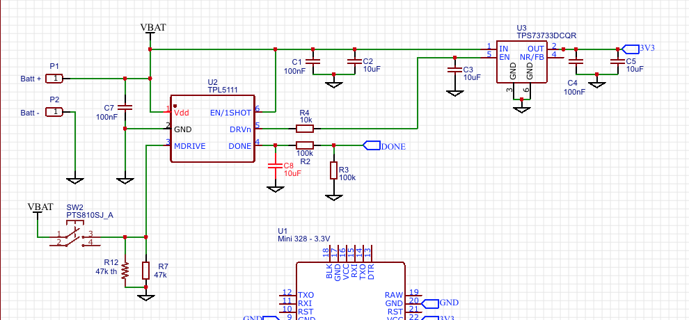
The concept of the TPL5111/TPS22860 works perfect (already tested with a the VT-S02C module), 10 years lifetime with a CR2032 !!! The big advantage of this concept is that the current drops down to a few (50) nA. In the TTN world your dutycycle is 1%, keeping your node for 99% dead saves a lot of energy. And… yes, maybe you have to put some information in eeprom before killing your node.
The big disadvantage is, that the dead time is fixed (by a resistor).
I will first say, I am not knocking the TPL poower on\off approach at all, it has its place, but its not a significant advantage in many circumstances.
The point of a node is to do something, not sleep all the time. The power it uses to wakeup, run the processor, read a sensor, send a transmission etc, consumes battery power and that far outweighs the current used in sleep. In many ways once the sleep current is below 5uA or so it becomes irrelavent. .
Compare a standard ATmega 328\1284 node thats running at 2uA in sleep, versus a TPL5111 controlled node thats using 0.1uA in sleep. If the node has a task that results in say a 5 year battery life with a pack of AAs, then the average current consumption is;
2800mahr/24hours/365days/5years = 63uA.
So using the TPL5111, versus a standard Atmega328\1284, would gain you 2/63 = 60 days of extra battery life in 5 years, not a lot really.
As for the dead time, then here is the advantage of say a TPL5110 as a wakeup timer. You can set the wakeup to a short period, say 10mins, then adjust the dead time to units of 10mins. The wakeup of processor from sleep, into a running state, with memory and LoRa device ready to go, is very much quicker (uses less power) than a full power down and restart …
The many different node applications are the reason that i have integrated a current bypass to make it possible to measure the total current over a certain time. Nice problem: measuring verry small currents (pA…nA…uA) with a short sample time to get the right picture.