In that case you can ask yourself whether an LDO is needed. Your node is energy efficient but the LDO will drain the battery.![]()
It may be useful to include some mounting holes in the PCB. I generally use a 3.0 mm or 3.2 mm hole in each corner and fit a plastic standoff to mount the PCB. This is obviously not needed if you have in mind another mounting arrangement.
For LiPo charging I have been using CN3065 breakouts. So far so good. I just need to make sure my panels don’t output too high a voltage when unloaded.
Missing from your schematic is a circuit to measure battery voltage, unless I missed it. As far as I’ve seen your options are a 100KOhm divider with a fet and 2nd I/O pin to turn it on/off or a 1M-4.7MOhm divider with a cap to allow stable readings. I use the latter successfully on STM32L0 boards (2x4.7M divider with 100nF cap).
In terms of low-voltage cut-off, I use the voltage divider and put the node into permanent sleep when it reaches 3.1v. Very little runtime left below that anyway. It takes some fiddling to get all the settings and I/O pins right to achieve the lowest consumption in sleep mode, so expect some experimentation and frustration! A single I/O pin in the wrong state can easily 10x your consumption when you’re in the single digit uA range. I would view any low-voltage cut-off in the regulator or charger as a second-level safety so wouldn’t worry about the exact voltage.
If you want the regulator with the lowest quiescent current, the TPS782 is down to 500nA. Only matters if you are really getting into single digit uA sleep. I would add a 4.7uF-10uF cap on the LDO output, btw, that radio takes a big drink when the TX turns on…
Something else I do on my low-power boards is to add a jumper on gnd where I want to measure current. This way I can add a shunt (uCurrent Gold in my case) to tune the sleep modes. I put it into gnd so the scope gnd, which you have to connect to one side of the shunt, is device gnd allowing me to hook probes to other pins to trigger the scope and show status/phases of the app.
2 Likes
@LoRaTracker you keep mentioning LiFePo4, can you provide some links to the actual batteries you use? I use small flat LiPo in the 200mAh-400mAh range, which fit wonderfully on the back of the tiny boards I use. I’ve looked into LiFePo4 over the years and the only smallish ones are 10440 cells (“AAA” size) which, with holder, add considerable bulk and cost as much as a small LiPo that is 2x-3x the capacity or as much as an 18650 cell (larger) that has 10x the capacity. Are 10440 cells what you use? Have you found a brand that is reliable?
NB: I’m not disputing the benefits of LiFePO4, I just haven’t found a compelling form-factor/capacity(/price) that would make me switch…
I have been using a Soshine AA LiFePO4, 700mAhr. They weigh in at 17.41g, which is the same weight as a LiPo of the same capacity.
To me, the safety issue is very important, I dont want trackers and things to catch fire,abuse in use is likely, so I avoid LiPos.
I would use LiPos if you built into a project an automated shut down system, in addition to the LIpos own protection circuit, but that adds extra components and size too.
One thought to consider, if you were selling your product to the general public, would you consider a design based on a LiPo\TP4056 adequate and what would your insurers think ?
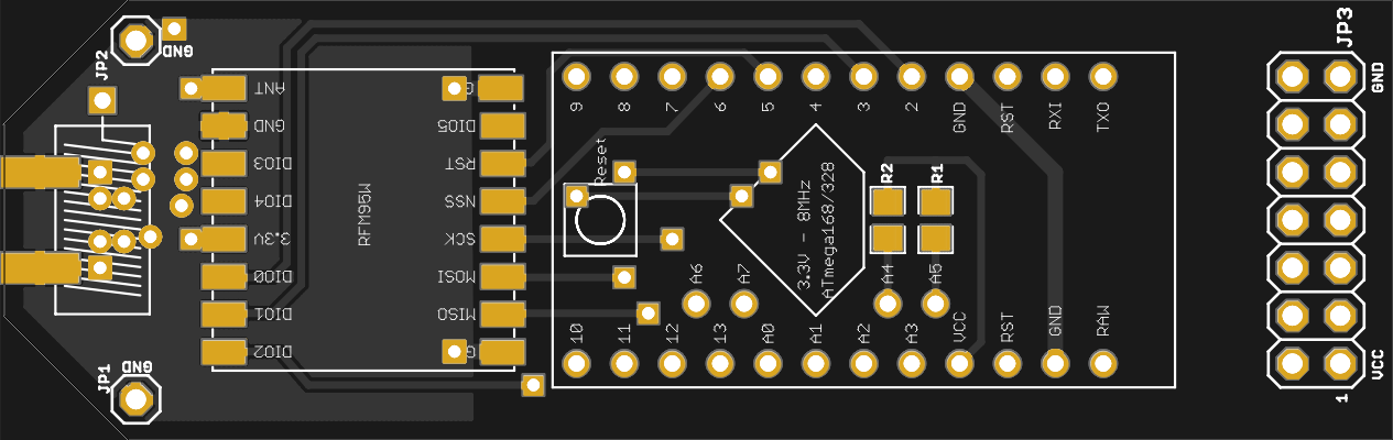
Well, the antenna connection doesn’t look good.
The traces are not laid out correctly and missing is a PI network for impedance matching.
Take a good look at several other designs to see how it should be done.
1 Like
Yes, look at other implementations from which to learn such as Adafruit’s LoRa Feather PCB. Thanks for sharing your progress.
I guess your PCB will probably work, i do have some tips.
Aside for the details of this specific design, i always add :
- Mounting holes. 3 mm, with the copper cleared form the holes.
- A version number on the silk screen and top and bottom copper. I start usually with 0.1.
- A date.
- A URL and logo.
Specifically for this design :
- Consider adding a ground plane.
- The antenna connector should be a close as possible to the radio module. I’d make the PCB a bit longer and move the connector to the center of the PCB edge. The trace should be as short as possible and the ground plane or wide traces are just as important as the antenna traces.
- Most of the texts are going to be under the arduino mini. Can you move them ?
Sparkfun have some tips on PCB design : https://www.sparkfun.com/tutorials/115.
Cheers, Ivo
well, this to me seems linear, and not an MPPT regulator…
true… the first chip I mentioned is 'true mppt and the cn3065 board from the picture is a cheap managed charger with build in protection, better and safer then the TP4056 but, if you live in a country with few sunhours and a lot of fluctuation choose a mppt charger.
* i’ve tested that little red module with an 750 mA lipo and solarpanel connected that worked well
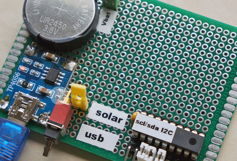
old experiment… charging a LIR2450 solar/usb with an adapted TP4056 module
2 Likes
The idea of powering unattended Lorawan sensors with MPPT is interesting, as it could probably reduce the required size of the solar panel, and the SPV1040 seems the good IC to fit the purpose! Unfortunately the only boards that I can find with this IC are expensive developer boards by ST, so unless we find someone that wants to engage with the challenge  , we would probably have to wait to check on this…
Thanks a lot for all your great input here! This seems like a really active and productive community.
I think a battery voltage sensor circuit would be a great addition. I have never build something like that (in code or in hardware), so if you could give me some pointers on how to design one for a lipo battery it would be great!
EDIT: Also it was mentioned that I should put a MCP1702 between the solar panel and the TP4056. Would that really improve things? I mean I could do that since I use the same chip on the output side already. I am just not sure if it would help that much.
@5774430de7caf50f006f, the RFM doesn’t really need a pi-network, and I think the OP probably doesn’t have the equipment to measure the parameter values needed to calculate the values of the pi-network components anyway. If you keep the RF-trace short and use a proper antenna, it will work like a charm.
However, what I would do is move the location for the edge SMA connector a lot closer to the RFM, and put that soldering hole for a wire or helical antenna in the center pad of the SMA-connector footprint. Shortens the RF-trace and saves space too.
And also IMPORTANT! Connect the GND-pin of the RFM right next to the RF-output pin to the GND-plane. It looks like it is unconnected…
@Algram There is a nice and simple way to measure the battery voltage which does not waste power. The method uses the fact that the digital outputs of the processor for a logical 1 go up practically to almost the Vcc voltage.
So what you do: you assign one digital output. You connect a resistor bridge that brings the voltage down to -say- one 1/4th (if your battery is 3.6V), and the output of that resistor bridge is connected to an analogue input, where you use the ADC to sample the voltage using the internal 1.1 Volt reference (!) as reference. Voila! Important is that the resistor bridge brings the battery voltage below the 1.1 Volt reference of course.
In your sketch you set the digital output to 1 when you want to do a measurement, you do one AD-conversion (or several, if you’d like to average), and then you set the digital output back to 0, so the circuit uses zero power when you are not measuring.
In our devices, we actually measure the battery voltage when the RFM is transmitting, because that is the maximum stress for the battery. So we send the TX-opcode to the RFM, wait for the RFM to start transmitting (typically takes several milliseconds), and then sample the battery voltage.
Hope this helps! If you implement this idea, you may donate me one can of Coca Cola Zero 
Hello guys,
If you are looking for a general purpose “Low Power Lora Node PCB”…?
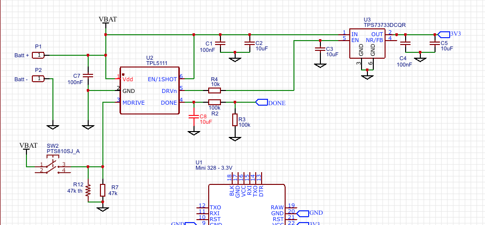
A second PCB is planned for different power sources, the power saving concept of TI (see: http://www.ti.com/tool/TIDA-00484 with the TPS61291, TPL5111 and/or TPS22860) and a scala of sensors (including GPS). See: http://alf4all.demon.nl/engineering/topics/digital_system_design/targets/Arduino-Pro-Mini_RFM95/index.htm
1 Like
looks fine 
I like the use of a TLP5111 to power on a microcontroller and RFM95W every x minutes. Standby current under 1 uA.
The TPLs are handy in some circumstances, but sometimes the loss of memory, when the CPU is turned off, may be an issue.
The TPL5010 can be used as a interrupt wakeup device and you can get a ATmega 328\1284 with LoRa device and regulator combo down to circa 1.5uA, benefit of this approach is that the memory status of the processor is retained.
1 Like
Give me hints what battery charger and or sensors has to be on the second PCB to make it as universal as possible. But… it must fit on the dimensions of the iot-lora board and his box.
The concept of the TPL5111/TPS22860 works perfect (already tested with a the VT-S02C module), 10 years lifetime with a CR2032 !!! The big advantage of this concept is that the current drops down to a few (50) nA. In the TTN world your dutycycle is 1%, keeping your node for 99% dead saves a lot of energy. And… yes, maybe you have to put some information in eeprom before killing your node.
The big disadvantage is, that the dead time is fixed (by a resistor).