Super Grateful for all posts on this Heltec CubeCell topic ![]()
Please can I ask the following questions regarding the AB02A.
As I am considering purchasing 10 or more of the AB02A units,
trying to evaluate IF & HOW they can achieve the following:
(I am newbie to coding/LoRa, been looking at general online related info for, 12 months on and off)
When looking at the examples in Arduino IDE - Arduino/File/Examples there is coding available,
but, am wondering how much of general arduino coding (there may be alot more helpful public/freeware sketches/coding examples) could be also useful for the cubecell users community.
Any advice on how to make use of this resource if it is possibly available and useful (If I knew how).
Also, (maybe helpful to other beginners) I saw a great blog on you tube that explains the purpose of the pins:
https://robojax.com/learn/arduino/2020Patreonuuythgt5463r.php?vid=robojax_Heltec_CubeCell-AB01
Please, another question, If using a transmitting cubecell unit (switch on/off signal into GPIO pin) to for example control a (GPIO pin activates relay switch out) on a receiving cubecell unit, If there is range issues between transmitter and receiver, can/how do I use another cube cell unit between the primary transmitter and receiver to extend the range (e.g go around a rock/cliff or generally achieve a ‘mesh’ network so all cube cell units can be used to enhance the overall transmission capacity within this modular system. Is there code available for other arduino that could be purposed for this that people know of?
As the AB02A has SMA versus IPEX antenna connection on AB02, but AB02A has no OLED,
any advice on plugging off the shelf OLED into AB02A serial & just getting existing code from the AB02?
Dunno if this post is excessive, but if can point beginners with these types of question to learning resources, could overcome ‘energy activation barrier’ and encourage more hobbyist/DIY projects in this exciting field, Thanks
Im not an expert, but this might help:
can regulate voltage increasing ‘boosting’ or decreasing ‘bucking’ with general DC electronics,
The following (example) might be worth checking out:
search aliexpress for: Adjustable2577 DC-DC Step Up
hope its useful
TTN and this forum are about LoRaWAN which is not a point to point or mesh network. For those applications please find another forum.
Hi everyone, might be a bit late, but is there a way to read the voltage (and eventually the current) provided by the solar panel I will use to power my HTCC-AB01 without using external components?
I read in the forum that the analog input of HTCC-AB01 can read up to 3.7V but the solar panel output may reach 5V so I guess I can’t just read the voltage trough an analog pin.
Feed the monitoring input via a resistor ladder network/voltage divider and simply scale values in your encoder/decoder accordingly. A 2:1 would allow you to monitor panel output up to nominal 7.4V. Be careful as solar panels under light/low/no load in full sun can go much higher than their rated nominal output so you may need to read specs and details and if needed arrange a suitable over voltage protection for the input.
Hello I am currently running a helium weather station with LHT65, LHT52 and IKEA Hack air quality sensor. Now I would like to integrate an anemometer via a heltec CubeCell HTCC-AB01. Maybe someone already has a sketch and a decoder that I can use? I’m not a programmer and need help.
Is there perhaps a good documentation on CubeCell programming?
Thank you and best regards
Sorry but this is the Forum for The Things Network not Helium…funded by TTI for the benefit of TTN & TTI/The Things Stack users…
You should try the Helium forum/discord.
Thanks for the hint. Helium is not the problem. I’m already planning to switch the weather station to TTS. My problem is that I’m looking for a sketch and a decoder to operate an anemometer. It is currently running on an Arduino UNO for testing and should then run on a CubeCell.
Who can help me? I’m not a programmer.
Many Thanks
Code:
#include <Wire.h>
#include <Adafruit_GFX.h>
#include <Adafruit_SSD1306.h>
#define SCREEN_WIDTH 128 // OLED display width, in pixels
#define SCREEN_HEIGHT 64 // OLED display height, in pixels
// Declaration for an SSD1306 display connected to I2C (SDA, SCL pins)
Adafruit_SSD1306 display(SCREEN_WIDTH, SCREEN_HEIGHT, &Wire, -1);
const int RecordTime = 3; //Define Measuring Time (Seconds)
const int SensorPin = 3; //Define Interrupt Pin (2 or 3 @ Arduino Uno)
int InterruptCounter;
float WindSpeed;
void setup()
{
Serial.begin(9600);
display.begin(SSD1306_SWITCHCAPVCC, 0x3C);
}
void loop()
{
meassure();
Serial.print(“Wind Speed: “);
Serial.print(WindSpeed); //Speed in km/h
Serial.print(” km/h - “);
Serial.print(WindSpeed / 3.6); //Speed in m/s
Serial.println(” m/s”);
display.clearDisplay();
display.setTextSize(1);
display.setTextColor(WHITE);
display.setCursor(0, 10);
display.println(“Wind Speed: “);
display.setCursor(0, 20);
display.println(WindSpeed);
display.setCursor(50, 20);
display.println(” km/h “);
display.setCursor(0, 40);
display.println(WindSpeed / 3.6);
display.setCursor(50, 40);
display.println(” m/s”);
display.display();
}
void meassure() {
InterruptCounter = 0;
attachInterrupt(digitalPinToInterrupt(SensorPin), countup, RISING);
delay(1000 * RecordTime);
detachInterrupt(digitalPinToInterrupt(SensorPin));
WindSpeed = (float)InterruptCounter / (float)RecordTime * 2.4;
}
void countup() {
InterruptCounter++;
}
The Arduino forums might be a better place to ask questions that are specific to Arduinos
And if your not a programmer then Arduino do have a forum where you can ask people to write code for you.
And if you aren’t a user of any word processing packages, please be aware of the code formatting tools like </> for any future posts.
As alluded to by @LoRaTracker, you are unable to suddenly find someone write the whole program for you, particularly on a LoRaWAN implementation on one of the more notoriously tricky devices.
Are you clairvoyant, or why do you say that?
A forum is there to ask for help.
It could be that maybe someone has implemented such an application before. After all, I’m asking my question in a CubeCell forum and not in the animal magazine!!
Thanks
Yes
Help yes, on this forum, do all the work, not so much.
Could be, the reality is that you’ve got the measurement script done. Sending sensor data is a well solved problem here, as that’s what LoRaWAN tends to be about - all you need to do is use the Heltec LoRaWAN firmware to send the WindSpeed value. If you need documentation on CubeCell programming, what is wrong with the materials on the Heltec website?
Alternatively you could use a ready made Dragino LT device that does pulse counting.
Not sure which editor you got the code from, but the libraries look like standard Arduino, so you would have to swap all the ” and ” characters for ".
The Arduino Adafruit libraries used do not appear to be compatible with CubeCell core in the Arduino IDE , so the code would need to be re-written for a known compatible library.
Well, not really. This is The Things Network forum. ![]()
The topic is CubeCell related though.
Hello, I read your post with interest.
Unfortunately, I’m not a programmer, so I’m looking for a ready-made program solution with a decoder for an anemometer (wind gauge) for my small weather station. I would then like to send the data to TTN and evaluate them graphically with ThingSpeak.
I’m looking for a sketch for a CubeCell board and the associated decoder (payload parser).
Do you have a sketch like that?
And do you know of such a project?
Thanks Uli
No, sorry. I use GxAircom as a weather station (open source).
Hi everybody, really stupid question here but I have been struggling all day without finding an answer online.
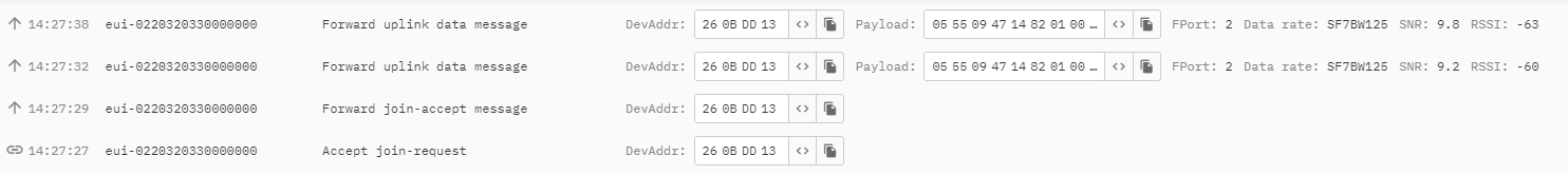
I am sending 13 bytes uplinks with the AB02 but on TTN i can only see 8 bytes (even if I copy the payload to my clipboard with the relevant button).
I am using ADR and UNconfirmed uplinks, the gateway is really close (i’m testing the system) and the datarate is SF7125.
At first I was sending messages once every 30 seconds (just for test purposes and for short periods of time) but now I have let it on for a bit less than a couple of hours with a message every 10 minutes but it didn’t change.
I tested decreasing the appDataSize to see if I was doing something wrong but it looks like fine (e.g if I put appDataSize = 4 i only see the first 4 bytes of my message. Howether if I set it again to 13 i only see the first 8 bytes on TTN).
Any clue on what am I missing?
Thanks a lot in advance
Need to see your code to understand what you are sending.
And please use the </> from the post formatting tools to post text of code

14:27:38 - 14:27:32 = 6 seconds you have barely allowed the RX window to close and you send the next uplink, you are hammering the FUP.
The appTxDutyCycle needs to be 600k to be 10 min
uint32_t appTxDutyCycle = 600000;
The elipsice in the screen shot implies that there is more data to see.
But first, please be kind to the community and give us some feedback on your understanding of the Fair Use Policy and why unconfirmed uplinks are normal and confirmed are very rare.
There is never any need to have a device transmitting on a schedule when you are developing - a push to send does everything you need and means you can keep up with the information on the console.
Thanks a lot for your fast answer.
I did use the right appTxDutyCycle, I already knew it was in milliseconds.
uint32_t appTxDutyCycle = 600000;
I don’t know why I have two uplinks in 6 seconds, maybe I disconnected it by mistake and reconnected it, but usually it sends the uplink every 10 minutes as it should be.
Concerning what I am sending it’s a 13 byte payload (I am sure it is because I print it on Serial Monitor before sending) containing some encoded sensor readings.