How to connect Utrecht E&A exhibition KISS LoRa to TTN?

:)):slight_smile:

Thx, good to know that kiss lora do function .

I noticed that a rather new gateway is used at the Mheen (RF-ILOC-18622 Rev. A0 )
Of course problems are expected from kiss lora device, its antenna, the software and so on.
But it is strange that “a connection” can’t be made at a close distance of about 200 m of the Mheen or the Kadaster gateway, that’s what is bothering me.

So small chance that some tuning is necessary.

Yes, It is a raspberry PI solution using the gateway code released by TTN.

I have to look in to the antenna specifications. It seems that antenna performance is not good.

I can explain that to you. Due to the opening angle of the antenna pattern You will have better reception in the main lobe of the antenna while bing outside of the direction of a antenna you will have poor reception.
The following image will visualise this.

2 Likes

thx for reply, I understand the picture and will conduct some experiments in following days. Keep you informed about results.

For everyone that wants to learn more about LoRa / The Things Network, there are quite some free Meetups coming along.

Utrecht: 13 June - Link
Enschede: 14 June - Link
Alkmaar: 27 June - Link
Apeldoorn: 28 June (@pe1mew probably has more info?)
Groningen: 28 June - Link
Amsterdam: 29 June - Link

The problem with the poor performance of the KISS LoRa is in a small but fatal design flaw.
If you look at the schematics you will see that a mistake was made with the antenna matching:

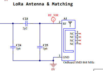
It seems the designer took the matching from the manufacturers application note:

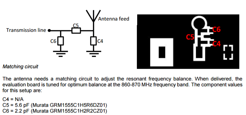
After inspecting the board we see that contrary to what the schematics say, C25 (C4 in the application note) is indeed not placed (which is correct). But C24 (C6) should have been 2.2 pF instead of 5.6 pF and C23 (C5) should have been 5.6pF instead of 2.2pF.

This accidental swapping of the two capacitors leads to a return loss of around -1dB. This means that more than 90% of the energy sent to the antenna is not radiated but returned. This totally explains that only gateways that are really close by receive the data from the KISS Lora.

We tried swapping the two capacitors and that improved the output significantly (to around -4dB), but it could be a lot better. This is because the matching circuit in the application note was for a board with a size of 120x 50 mm.
Since the KISS LoRa is not exactly this size (and quite an odd shape …), antenna matching should have been done specifically for this board.

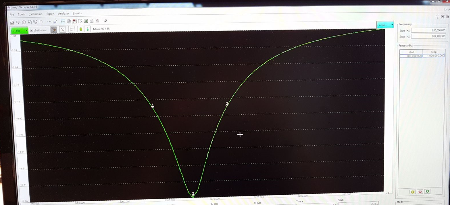
We didn’t spend all that much time on trying to match, but replacing C23 by an inductor of 10nH we managed to bring the loss at 868 MHz down to -12dB. This could even be improved further (we use the same antenna in our own designs at SODAQ and typically get it down to -20 dB (see picture below).

So the boards can easily be fixed (well for the ones that are comfortable soldering 0402 components).

Jan Willem Smeenk
Chief Tinkerer @ SODAQ

disclaimer: SODAQ has in no way been involved in the design and production of the KISS LoRa.

8 Likes

So that explains a lot of Kiss Lora problems
Question: how did you noticed that 2.2 and 5.6 were swapped on the circuit board. I can not find any indication on the capacitors.

So your suggestion is to relace C23 C5) with an inductor of 10nH (have to buy or make one).
Do you mean C24 (C6) 2.2 pF or 5.6 pF

hw- geitz suggested to use a quarterwave antenna (see above)
What is better in your opinion

Hey Jelle,

I did the antenna measurements, so I’ll tell you what components I used.
C23 should be 5.6pF, like it says in the datasheet of the antenna, and I changed C24 to an inductor of 10nH, and C25 should remain unpopulated. I only spent about 20 minutes on this measurement and tuning process, and I didn’t have the right inductors in stock to get the perfect match, but we still got -12dB return-loss, and this is pretty decent (around 95% of energy absorbed by antenna)

To measure the antenna, I did the following:

I first removed the RN2483 module, and soldered a semi-rigid coax cable to the RF feed and ground of the module:

I calibrated my VNA, and this is the return-loss plot of the default matching:

The marker labeled ‘1’ is set at 868 MHz, and you can see that the return-loss is around the 0dB line, meaning that almost all of the energy is reflected. I then took off the components, and soldered a 5.6pF capacitor on C23 and a 2.2pF capacitor on C24 like they recommend in the datasheet

Here you can see the return-loss plot with the matching components from the datasheet:

This is pretty close, but not good enough. I finally changed C24 to a 10nH inductor, and I got the following result:

If you have any questions, let me know.

Regards,

Nick Leijenhorst
SODAQ

2 Likes

Thx for the explanation
I’l try to buy (or make ) the 10 nH indictor.
Rf has always been a kind of black art for me :))
More comfortable with slow digital signals and killing Rf interference in amplifiers
But I understand your explanation
Looks like a stupid mistake or … in order to promote buying gateways, it was a clever move :))

ps added SODAQin my contactbook of coarse

@nickleijenhorst
Today i swapped both capacitors and the first check learned that my signal dropped by 5 dB. It suggests a decrement in performance of my gadget. :frowning2:. I have to verify in a better manner because surroundings do influence too.

@Jelle007
I ordered 10 smd inductors. wannahave one? We dont live apart too much :boy:

We have a modified KISS gadget and a ‘standard’ one here at the office, tomorrow we’ll perform multiple RSSI measurements to see how much difference the change makes! I want to see more gateways :wink:

2 Likes

that would be very nice
(van Essen has non)
Please let me know how, when etc.
(jelle.vanderlinde@gmail.com)

May be during assembly supplies were changed during a run.

I agree :))
May be you can also test a simple 8.x cm wire antenna directly connected to rf out

@nickleijenhorst, thanks for the research I thought 90% reflection was very pessimistic but graphsdon’t lie -)
I am very interested in this topic but it is not clear to me what you are measuring. Correct me when I’m wrong but in theory a slighty damage / malformation of the antenna could also cause a mismatch and even when you replace the RN2483, the metal housing may affect the measurements?

Hey Marco,

I’m measuring S11, also known as return-loss, or basically: how much energy is reflected from the antenna. Typically, people aim for -10dB (10%) or less. -20dB would mean that 1% of the energy is reflected back to the LoRa module.

I have thought about the effect of the shield of the LoRa module, but I think the effect will be negligible. The antenna mostly interacts with the ground plane below it, and there also fringing electric fields around the antenna element, but the proximity of the LoRa module shield should not influence the return-loss by more than 1dB for example. I could try measuring this, but then I’d have to cut the trace between the LoRa module and matching network, and I don’t want to do any destructive testing yet :slight_smile:

A malformation of the antenna will also affect the return-loss, but I think you’d have to do quite some damage before you’ll notice the effects… If your antenna is bent, you can probably bend it back into shape :wink:

Regards,

Nick Leijenhorst

1 Like

how did you managed to remove the RN2483 module (and get it in place again)
I quess it can’t be done with my aged soldering station :))

I don’t see any marks on the capacitors, so i assume you measured the capacity

I used a hot air soldering station, spent some time pre-heating the entire board, and then I focus all the head around the LoRa module. Usually the shield comes off first, so I take it off carefully. Then I can focus the heat on the PCB of the LoRa module, and take that off.

I think you can re-solder the same LoRa module, but I usually grab a new module because you have to use quite a lot of heat to get the thing off…

I didn’t measure the capacitors, I just swapped them to see if it made a big difference, and it did :wink: Measuring capacitors that small is nearly impossible…

Maybe something like this: https://www.youtube.com/watch?v=gQda5iibZos, but if you are in for a real challenge, try this: https://www.youtube.com/watch?v=tlSY1uaw0GA But indeed I love to hear how it was done in this case. I guess SODAQ has some nice equipment for it we don’t have all at home (still working with this :laughing:)

It’s just a simple hot air soldering station, you can pick one up for like ~80 bucks :slight_smile:

Hi All,

For what it is worth.

For a week the gadget worked fine. Last wednsday night the onboard accu did run empty.
During thirsdat evening I had time to charche the accu again.
The gadget restarted and did not made any connection anymore to the accespont.
The following happens when I switch the gadget on (rotery on 0) the bottob led blink 10 times then turns gree/orange for 10 sec and goes off. the iot blue led blinksevery 25 sec or so short.
Today I hookup the gadget to a terminal and only saw

Sending: mac join otaa
Response is not OK: no_free_ch
Send join command failed
Sending: mac join otaa
Response is not OK: no_free_ch
Send join command failed

Tryed to reset it a few times no luck.

Did a fresh upload froim the arduino scetch ( with the modded keys).

Did a commisioning=> this went well.
Applications > kiss-lora-hw-geitz > Devices > kiss-lora-device-xxx > Settings I copied the keys from the scetch. and the gadget start working again.

The gadget was out of power for 18 hours or so…