There is no connection. LoRaWAN is not WiFi where a system connects to an accesspoint, LoRaWAN is a broadcast network where every receiver (gateway) within range gets the data and if there are no receivers in range no-one gets the data. As a result you will not get an indication whether data has been received or not as the gadget does not know if there are any gateways receiving the data.
There is a way to get an indication whether data is received, you need to use confirmed transmit for that purpose. When using confirmed transmit the back-end will instruct a gateway to send a confirmation packet to your node (gadget). However, the access policy of TTN limits this to max 10 acknowledgements each day.
Receiving by a gateway is never reliable. It always depends on (too) many variables like atmospheric conditions, type and build of gateway, antenna placement, type and build of node and antenna placement of the node, any foreign bodies (metal, human or otherwise) near the antennas.
That is why (in my opinion) LoRaWAN should never be used when lives depend on the communication succeeding.
I got my gadget on the first day of the E&A. And it works from the start.
Here in the North of Apeldoorn most of the time it connects to the gateway
at the Kadaster building and sometimes to that of the Mheen.
@Jaapbr
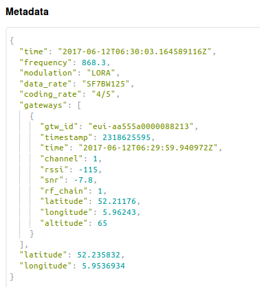
I looked up your position in the json you provided.
The area you live will not have highest level of coverage. Especially not for SF7.
I propose to lower to SF9. that will increase probability of coverage I expect.
PS: There are currently no plans from the community of Apeldoorn to build aditional gateways in that area. Unfortunately for you the current focus is on the south.
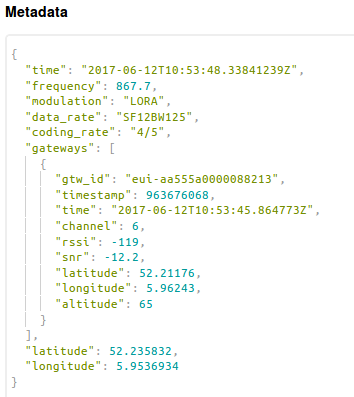
@Jelle007 I looked up your position in the json you provided.
The area you live has good coverage. However the received signal strength of your node indicates that you have poor coverage. Probably because you a are indoor, at ground floor level, or you antenna is obstructed.
These are all factors that count.
I am not sure if ADR is enabled in the gadget. In the TTN library ADR is not enabled by default.
My suggestion is to switch on ADR and see how the network optimises the link.
I tried it outdoor for 2 days: no succes
Indoor in my study room (south of the building) i get sometimes a "connectioin"for about 2-7 hours
In the attic (north, 10 meters high, only singele glass window) ) i got after 9 hours a "connection for 1 hour.
Kiss Lora has the original sw
I tried different board positions but can’t determine which direction gives the best coverage.
So first I’ll try attic south side, repiar my steam engine and at the end of the week I will try to fix the sw (must first get acquainted with Arduino .
I presume that Kiss Lora demonstration SW (or hardware) could be incompatible with the two gateways i tried in Apeldoorn ( tried 6 times at a distance of about 100-200 m, a restart and join request was not accepted within 5 minutes)
PS the old Juliana Church at the Deventerstraat would be an ideal location :))
I ordered some arduino and lora stuff in order to experiment.
It is an interesting development
I guess it is beause of your location. The location you suggest is in the middle between two high gateways at > 3 km of both gateways. From planning perspective not a good idea at this moment. Maybe later when LoRaWAN starts to suffer from high load.
I noticed that a rather new gateway is used at the Mheen (RF-ILOC-18622 Rev. A0 )
Of course problems are expected from kiss lora device, its antenna, the software and so on.
But it is strange that “a connection” can’t be made at a close distance of about 200 m of the Mheen or the Kadaster gateway, that’s what is bothering me.
Yes, It is a raspberry PI solution using the gateway code released by TTN.
I have to look in to the antenna specifications. It seems that antenna performance is not good.
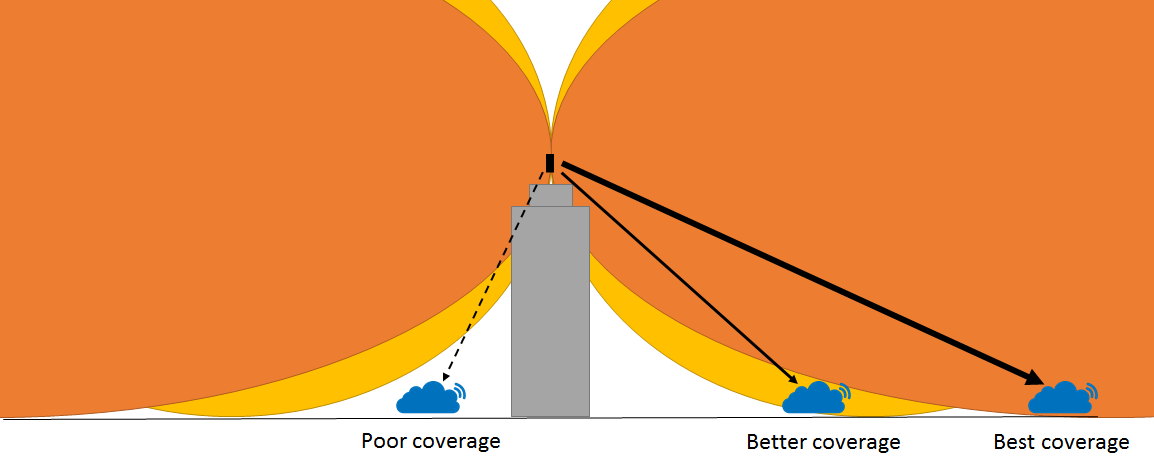
I can explain that to you. Due to the opening angle of the antenna pattern You will have better reception in the main lobe of the antenna while bing outside of the direction of a antenna you will have poor reception.
The following image will visualise this.
For everyone that wants to learn more about LoRa / The Things Network, there are quite some free Meetups coming along.
Utrecht: 13 June - Link Enschede: 14 June - Link Alkmaar: 27 June - Link Apeldoorn: 28 June (@pe1mew probably has more info?) Groningen: 28 June - Link Amsterdam: 29 June - Link
The problem with the poor performance of the KISS LoRa is in a small but fatal design flaw.
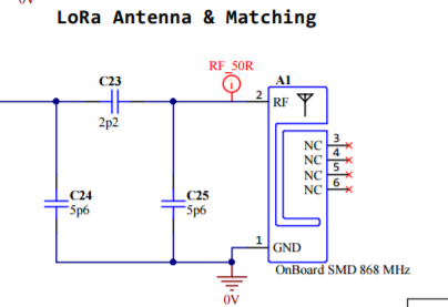
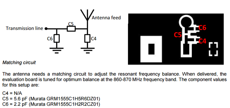
If you look at the schematics you will see that a mistake was made with the antenna matching:
After inspecting the board we see that contrary to what the schematics say, C25 (C4 in the application note) is indeed not placed (which is correct). But C24 (C6) should have been 2.2 pF instead of 5.6 pF and C23 (C5) should have been 5.6pF instead of 2.2pF.
This accidental swapping of the two capacitors leads to a return loss of around -1dB. This means that more than 90% of the energy sent to the antenna is not radiated but returned. This totally explains that only gateways that are really close by receive the data from the KISS Lora.
We tried swapping the two capacitors and that improved the output significantly (to around -4dB), but it could be a lot better. This is because the matching circuit in the application note was for a board with a size of 120x 50 mm.
Since the KISS LoRa is not exactly this size (and quite an odd shape …), antenna matching should have been done specifically for this board.
We didn’t spend all that much time on trying to match, but replacing C23 by an inductor of 10nH we managed to bring the loss at 868 MHz down to -12dB. This could even be improved further (we use the same antenna in our own designs at SODAQ and typically get it down to -20 dB (see picture below).
So the boards can easily be fixed (well for the ones that are comfortable soldering 0402 components).
So that explains a lot of Kiss Lora problems
Question: how did you noticed that 2.2 and 5.6 were swapped on the circuit board. I can not find any indication on the capacitors.
So your suggestion is to relace C23 C5) with an inductor of 10nH (have to buy or make one).
Do you mean C24 (C6) 2.2 pF or 5.6 pF
hw- geitz suggested to use a quarterwave antenna (see above)
What is better in your opinion
I did the antenna measurements, so I’ll tell you what components I used.
C23 should be 5.6pF, like it says in the datasheet of the antenna, and I changed C24 to an inductor of 10nH, and C25 should remain unpopulated. I only spent about 20 minutes on this measurement and tuning process, and I didn’t have the right inductors in stock to get the perfect match, but we still got -12dB return-loss, and this is pretty decent (around 95% of energy absorbed by antenna)
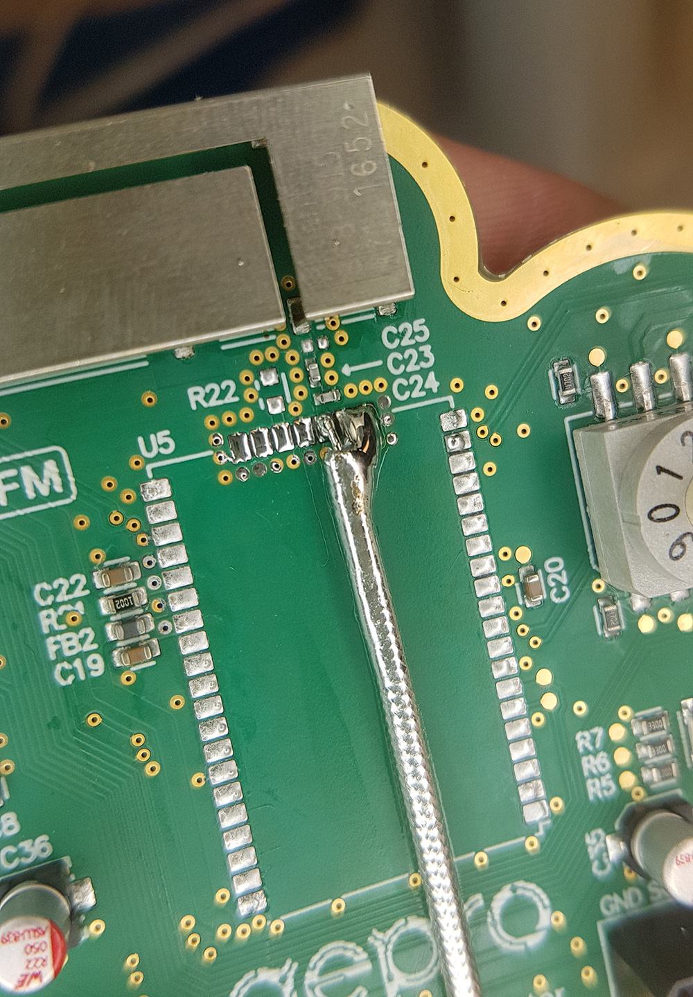
To measure the antenna, I did the following:
I first removed the RN2483 module, and soldered a semi-rigid coax cable to the RF feed and ground of the module:
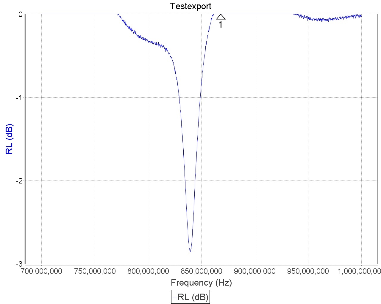
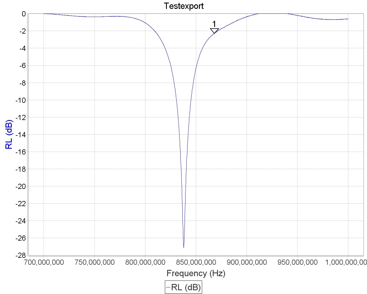
I calibrated my VNA, and this is the return-loss plot of the default matching:
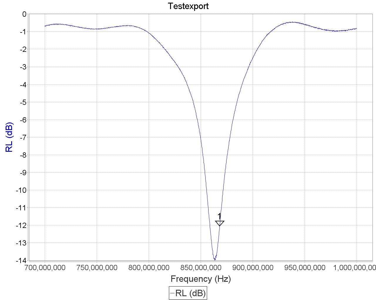
The marker labeled ‘1’ is set at 868 MHz, and you can see that the return-loss is around the 0dB line, meaning that almost all of the energy is reflected. I then took off the components, and soldered a 5.6pF capacitor on C23 and a 2.2pF capacitor on C24 like they recommend in the datasheet
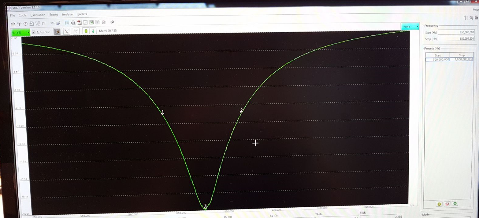
Here you can see the return-loss plot with the matching components from the datasheet:
This is pretty close, but not good enough. I finally changed C24 to a 10nH inductor, and I got the following result: