Thx for the explanation
I’l try to buy (or make ) the 10 nH indictor.
Rf has always been a kind of black art for me :))
More comfortable with slow digital signals and killing Rf interference in amplifiers
But I understand your explanation
Looks like a stupid mistake or … in order to promote buying gateways, it was a clever move :))
@nickleijenhorst
Today i swapped both capacitors and the first check learned that my signal dropped by 5 dB. It suggests a decrement in performance of my gadget. . I have to verify in a better manner because surroundings do influence too.
@Jelle007
I ordered 10 smd inductors. wannahave one? We dont live apart too much
We have a modified KISS gadget and a ‘standard’ one here at the office, tomorrow we’ll perform multiple RSSI measurements to see how much difference the change makes! I want to see more gateways
@nickleijenhorst, thanks for the research I thought 90% reflection was very pessimistic but graphsdon’t lie -)
I am very interested in this topic but it is not clear to me what you are measuring. Correct me when I’m wrong but in theory a slighty damage / malformation of the antenna could also cause a mismatch and even when you replace the RN2483, the metal housing may affect the measurements?
I’m measuring S11, also known as return-loss, or basically: how much energy is reflected from the antenna. Typically, people aim for -10dB (10%) or less. -20dB would mean that 1% of the energy is reflected back to the LoRa module.
I have thought about the effect of the shield of the LoRa module, but I think the effect will be negligible. The antenna mostly interacts with the ground plane below it, and there also fringing electric fields around the antenna element, but the proximity of the LoRa module shield should not influence the return-loss by more than 1dB for example. I could try measuring this, but then I’d have to cut the trace between the LoRa module and matching network, and I don’t want to do any destructive testing yet
A malformation of the antenna will also affect the return-loss, but I think you’d have to do quite some damage before you’ll notice the effects… If your antenna is bent, you can probably bend it back into shape
I used a hot air soldering station, spent some time pre-heating the entire board, and then I focus all the head around the LoRa module. Usually the shield comes off first, so I take it off carefully. Then I can focus the heat on the PCB of the LoRa module, and take that off.
I think you can re-solder the same LoRa module, but I usually grab a new module because you have to use quite a lot of heat to get the thing off…
I didn’t measure the capacitors, I just swapped them to see if it made a big difference, and it did Measuring capacitors that small is nearly impossible…
For a week the gadget worked fine. Last wednsday night the onboard accu did run empty.
During thirsdat evening I had time to charche the accu again.
The gadget restarted and did not made any connection anymore to the accespont.
The following happens when I switch the gadget on (rotery on 0) the bottob led blink 10 times then turns gree/orange for 10 sec and goes off. the iot blue led blinksevery 25 sec or so short.
Today I hookup the gadget to a terminal and only saw
Sending: mac join otaa
Response is not OK: no_free_ch
Send join command failed
Sending: mac join otaa
Response is not OK: no_free_ch
Send join command failed
Tryed to reset it a few times no luck.
Did a fresh upload froim the arduino scetch ( with the modded keys).
Did a commisioning=> this went well.
Applications > kiss-lora-hw-geitz > Devices > kiss-lora-device-xxx > Settings I copied the keys from the scetch. and the gadget start working again.
I posted a problem under the topic “single channel gateway” but after reading this topic I think it would be better posted here (because it seems to be a KISS LoRa problem). So I post a link to it: Single Channel Gateway part 2
Maybe I 'm one of the lucky guys. My E&A Kiss Lora gadget is functioning from the beginning. I haven’t changed anything in the device. The position/surounding of the gadget for a good operation is critical.
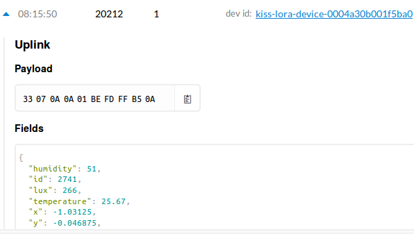
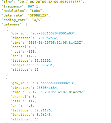
Below some last results:
After studying the doc’s of ProAnt I decided to turn my Kiss LoRa gadget from the Vo-plane to the V90-plane. The performance is changed, specially the snr for the two connected gateways. See the screenshot of the TTN-console. Also there are not many packetlosses anymore.
Thanks for the suggestion , I guess the documentation you talk about is here, and then especially the “Application note 868 (PDF)”?
Swithing form V0 to V90 plane means positioning the KISS-Lora gadget “upright” with the bottom of the cloud “on the floor”? So the cardboard stand that was delivered is not only provided to make the KISS LoRa look nice?
Placing the KISS gadget flat on a table should provide the best omnidirectional radiation pattern. You can see that when the board is flat, the gain pattern on the horizontal plane is omnidirectional. I do have to say, the datasheet is a really non-standard way of showing the radiation pattern… Including a 3D gain pattern would already help a lot. But the PROANT-868 is basically an inverted-F antenna above a ground plane, and vertically polarized when the PCB is placed on a table for example. Correct me if I’m wrong.
That would be the orientation corresponding to the H-plane graph in chapter 7 of the Application note 868 ? I was just trying to interpret the suggestion that @JBraam made, but looking at the graphs It seems that the “H-plane position” should be best indeed. So hope Jaap can shed some light on his decision and observations.
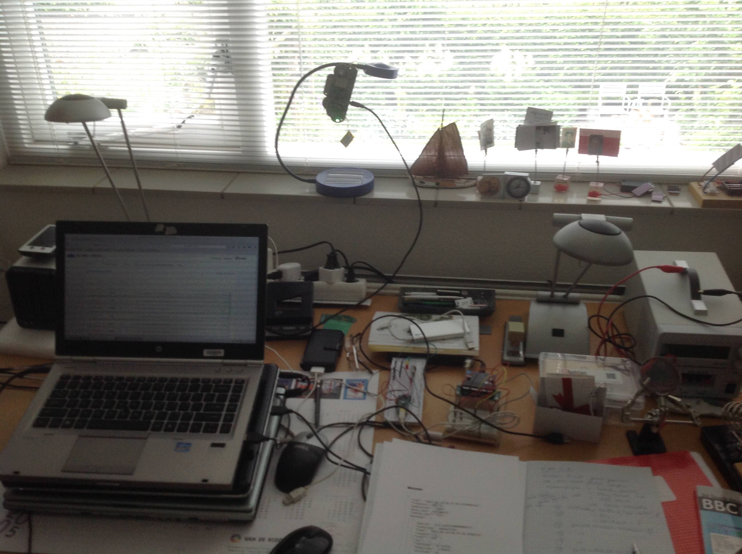
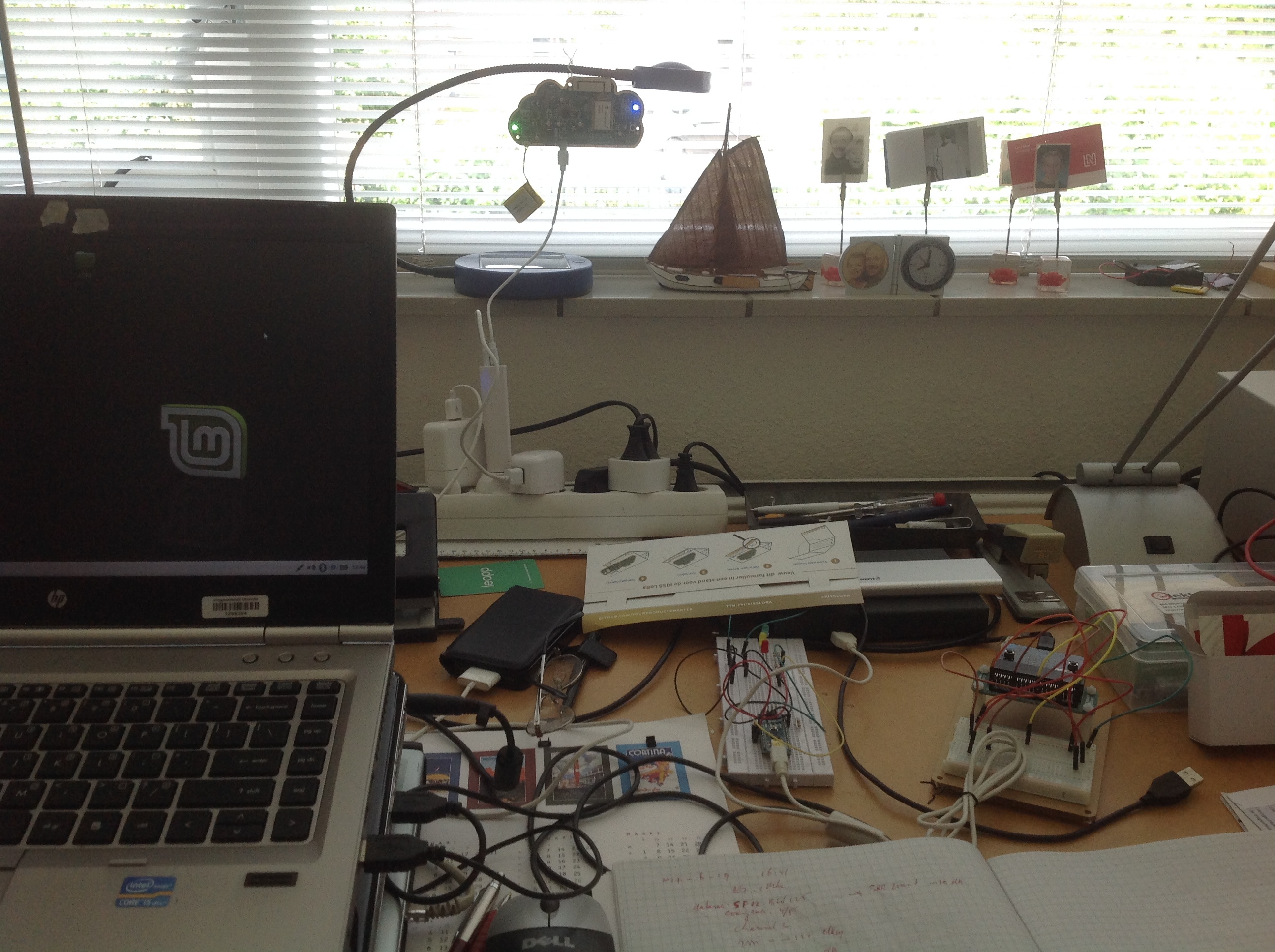
The KissLoRa hangs on a solar powered lamp.Picture 1: V0-plane, pcture 2: V90 plane.
Because I wanted some gain in the direction of “The Kadaster-gateway”.
Picture 1
Picture 2
Indeed I used: Application note 868 (PDF)".
Now the gadget works ok, I’ll look at the software.
 . I have to verify in a better manner because surroundings do influence too.