Hi all, I am new to this and I have some basic questions. I am trying to create an end node to send a hello world message to my application using a Lambda 9s (suggested by my teacher) and an Arduino pro mini. I use the LMIC library from IBM and I use the example for ttn-abp. I modified all the fields in config.h to match the frequency used in my region. However, as soon as I upload my code, it starts and fails immediately. I checked my connection over and over again, however it is still not working.
For reference, here is the youtube tutorial I am following:
I would test the setup using an example sketch from one of the Arduino point to point LoRa libraries, these normally do a connection test to the LoRa module at startup, so you can check if its connected up OK.
I have a standalone Arduino sketch, no LoRa library needed, which will check that the Arduino can read the LoRa device, it works with DIO0, DIO1, DIO2 and NRESET not connected … if your interested …
The significant difference between the SX1272 and SX1276/8 is that the polarity of NRESET is inverted. However the SX127X is fairly ambivalent about the NRESET pin, and you will mostly find that if the pin is disconnected, the LoRa device works just fine at power up.
It’s getting there, but we don’t know precisely which code you are using and whilst I’ve read the source several times and have a rough idea what’s on line 691 of radio.c, I’m not going to guess because that won’t help.
A permalink to the line in GitHub will help enormously, given that the volunteers have many things to do and not enough time.
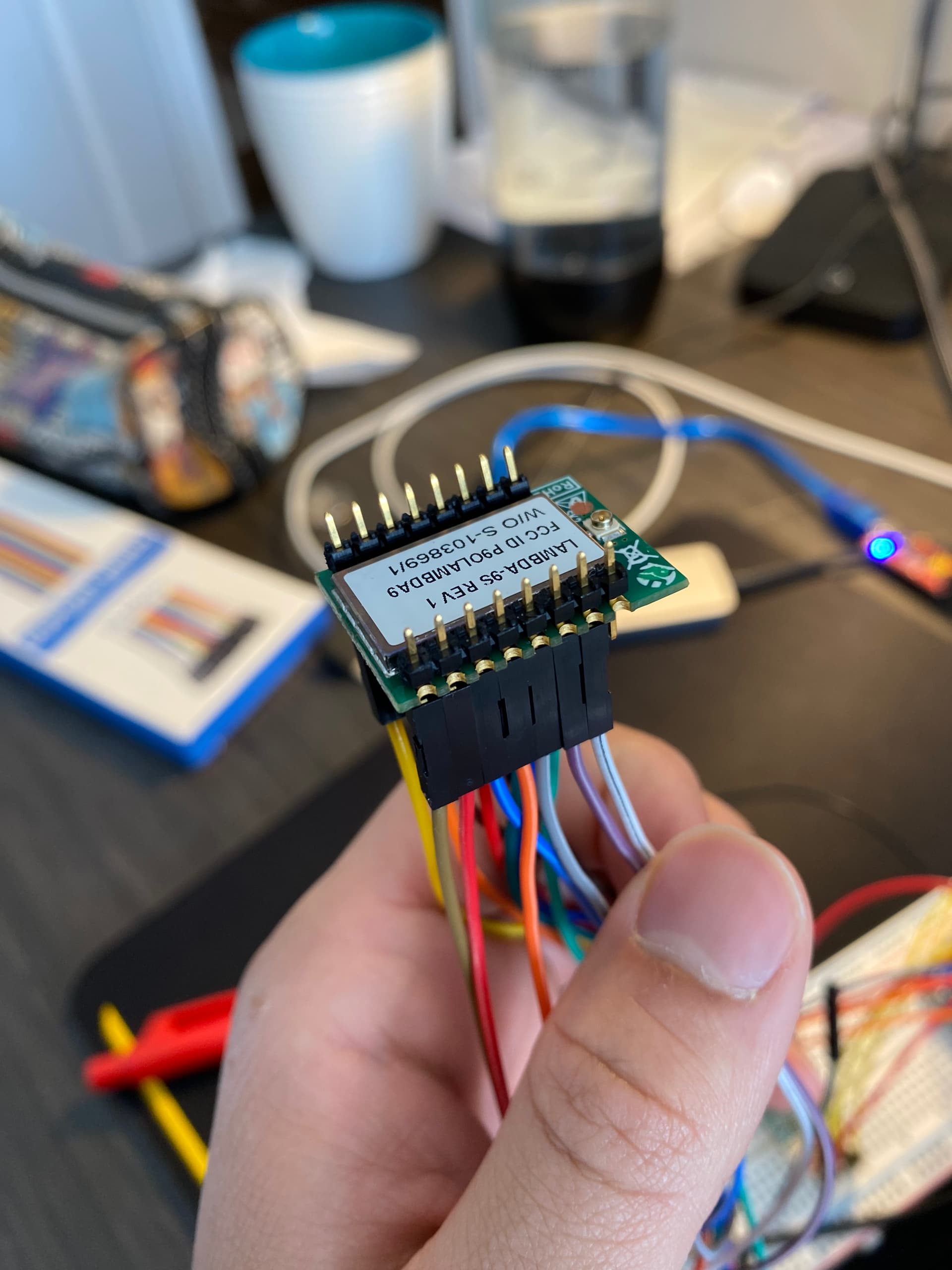
Hi thank you so much, yes I will try it right now. I was wondering if you have a link where I can see the examples. Moreover, I want to ask if my connection might be the issue since it is not soldered?
Has test sketches called ‘2_Register_Test’ (for SX127X, SX126X and SX128X) that are standalone (on purpose!) LoRa device checkers. You dont need to install the Arduino library just use the sketch. The sketch will print out the LoRa device registers and samples of what to expect are in the comments included in the sketch. As per the sketch notes, leave the NRESET and DIO0 pin of the LoRa device not connected.
On an ATmega processor, such as the Arduino Pro Mini, you can leave the NRESET and DIO pins connected, since these do default to inputs and are thus floating and do not affect the test sketch.
Your using Dupont wires to connect the LoRa module, and for the example test sketch I suggested to work you do only need to connect, GND, VCC, SCK, MOSI, MISO, NSS. Leave all other pins disconnected.
And for the 1% of the time that it does work, it will stop working within one micro-fortnight.
Looking at your picture, you do not appear to have connected NSS/nSEL, so the module will never know that it’s being talked to which is pretty much the same as the module not being found. Which is just as well as you do not have an antenna connected which runs the risk of destroying the output stage. You will need to tell LMIC about the Tx/Rx RF switch which will require you to alter LMIC to cope with the two pins on the radio module as the library only supports a single pin for the switch.
You define which radio module you are using in config.h. The asserts in radio.c are mostly about key registers being correct, perhaps you can verify with the permalink suggestion?
The video uses an SX1276, you may be better served to return the high priced RF Solutions module and get an RFM95. Or lookup LMIC-node on GitHub that has instructions & support created by one of the forum moderators.
Hi, so I also have a RFM95. I soldered the wires and I connected the following:
GND of RFM95 to GND of arduino pro mini
3.3V of RFM95 to Vcc of arduino pro mini
MISO to pin 12 of arduino pro mini
MOSI to pin 11 of arduino pro mini
SCK to pin 13 of arduino pro mini
NSS to pin 10 of arduino pro mini
Then I ran the example test sketch and still no device detected. The RFM95 I have is brand new, and the soldering is tight. Do you know what might be the issue?
Yes, I just noticed that in the picture the NSS was not connected, I think the dupont wire unconnected while I took the picture. Okay thank you, I will install the antenna, do you know which one would be good? I also have an RFM95 with me. I tested the example given by LoRaTracker but no device was found.