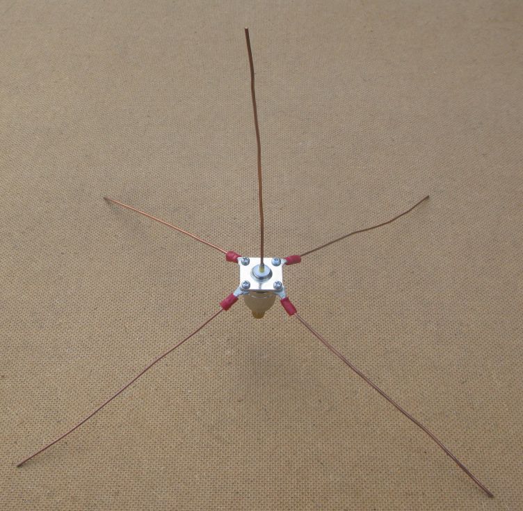
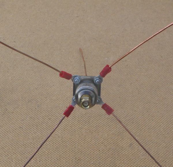
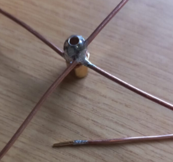
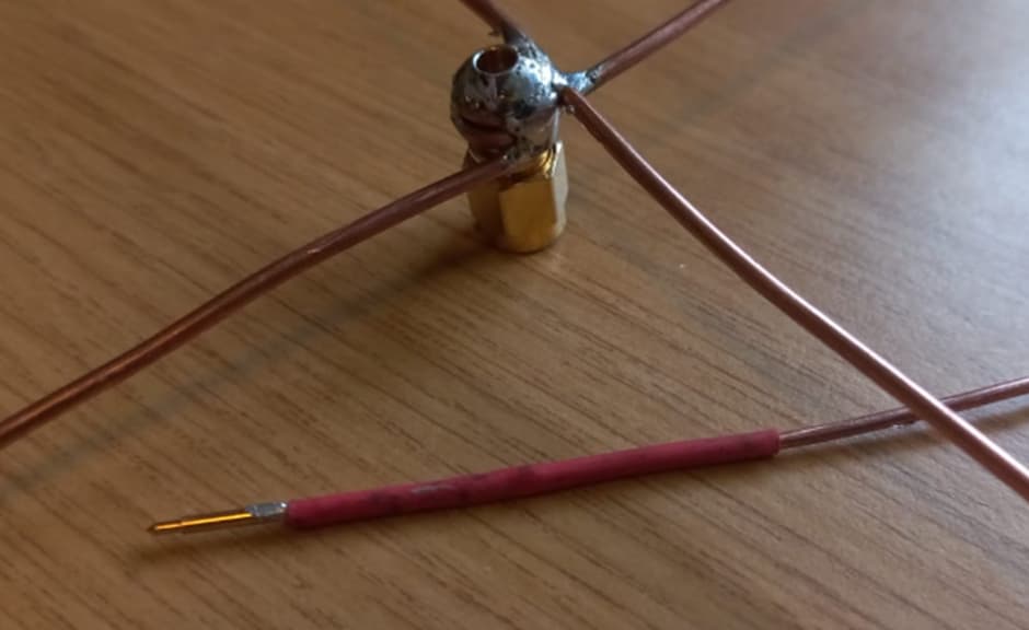
I cannot find my 868Mhz one either, but here are pictures of my 434Mhz one, build is the same, just use different wire lengths.
Using Guitar wire is OK for HABs, light weight etc, but the ends are very pointy and it can be difficult to solder. Simple copper wire extracted from a bit of (not live!) mains cable is easier to build with, and you can use solder tags to attach rather than crimp. And if you want to pack it away, uncrew the solder tags.
That antenna is quite difficult to get wrong, so Joe in Australia should get the same performance in a large field as Fred in the UK, so global antenna comparisons should be valid.
Its so easy to build, you dont really need instructions. Its uses an N-Type chassis socket.
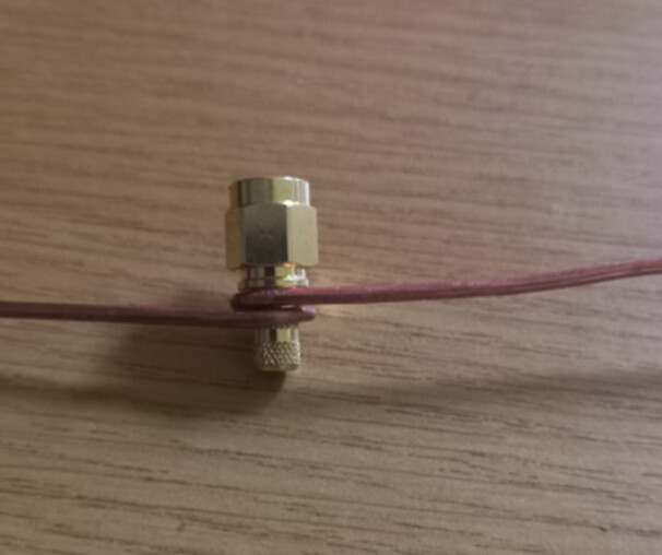
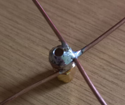
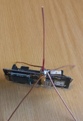
As you have the crossover mounted to the side of the SMA it is likely unbalanced wrt polar plot and with slightly deminished SWR…unless you have tuned and balanced each arm. Best is get the crossover point over the hole and take the vertical up from there… also IIRC the ‘arms’ create a virtual ground plane for the vertical and having it mounted directly over the pcb/components will further unbalance and detune. Best is use a short stub cable - say 4-8cm long to another sma connector to mount to the pcb sma - that will lift the arms clear and improve performance (Again IIRC - I need to go check old designs from a few years back )
Indeed, the point of using a simple referance antenna, is that its just that; a reference and simple to make. Its useful if the reference used is the same the World over, but its absolute performance to fractions of a dBm does not really matter.
If you comparing a series of antennas, A, B, C and you just want to know which is the best, then you dont really need a reference in the first place.
If you attempt to idealise the construction, using co-ax cables and the consequent ferrite rings as chokes etc, you just turn something simple into something not simple, types of co-ax, lengths, types of ferrite rings etc.
An additional benefit of a standard (and simple!) reference is that you can come up with a reference performance standard that allows you to know, without using absurdly compex equipment, if the LoRa devices are actually working correctly. If using the standard easy build reference antennas with them say 2M off the ground, and transmitting at say, 14dBm and 50m away I get an RSSI of -60dBm in the UK, Franz in Germany has a problem with one of their devices if they only get -70dBm.
+1 for that! Lol. Indeed. and since this is Canada, I’m going to have a nice snow-load shortly… The fluffy stuff always does “interesting” things to radio waves!
Does anybody have experience with the iOS app for Laird?
I took the sensors home (7Km away) again. I wanted them to roll back to lowest data rate so I could do a range test Monday morning on the way to work.
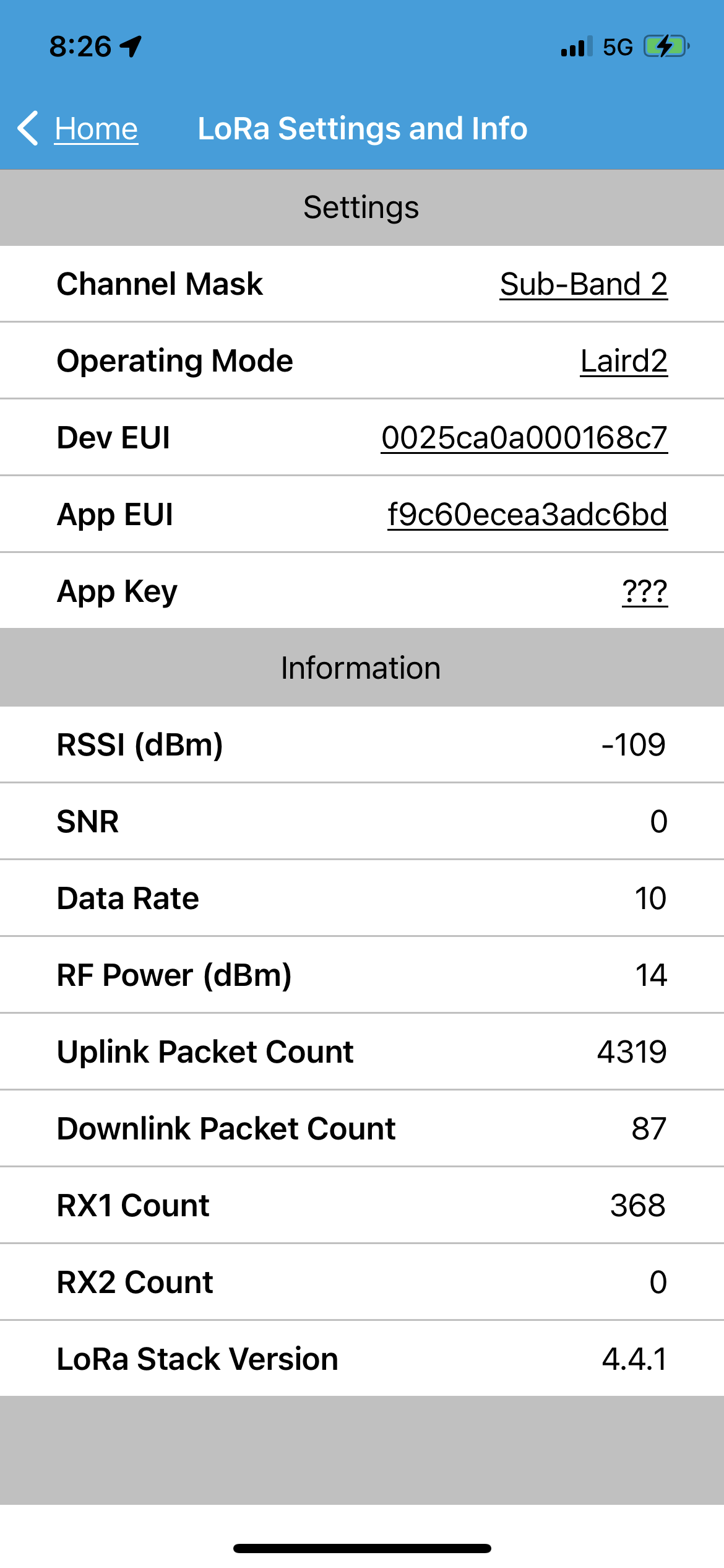
The LHT65 seemed to go offline. The Laird seems to be talking to a Gateway, but not mine!
The pic is the LoRa status in the iOS app.
How do I tell from that, or any other screen, if the LAIRD is able to connect to a gateway? And, since that gateway likely will not be forwarding to the cloud I’m on, I assume it wont get a reply?
Or maybe more generally, is there a way to tell the LAIRD sensor is getting replies from a gateway?
What do you see in the Console - Application - Live Data?
What do you see in the Console - Gateway - Live Data? (your gateway)
What is your gateway ID, is it on line all the time?
If you look in Console - Application - Live Data and you expand the uplink message you will see all the metadata, including information about the gateways you are using to connect to the NS.
LoRaWAN devices connect to a network server, not to a gateway. LoRaWAN is not WiFi.
Any TTN connected gateway in range of the RF transmission will forward the data to TTN.
Well it’s a very high priority item for the community - adhering to the FUP isn’t hard and you’ve been given the key materials of what it is and how to calculate it.
It is not a reference antenna, if the SWR is not ideal and bit unbalanced it will be the same in all test. So giving the same reference point.
You will not only need to improve the antenna and coax if you want to do calibrations, you will need to improve the housing of the node, shield it and better design on the RF on the PCB.