Hi Guys,
In a previous thread today, I had some problems migrating my custom hardware from v2 to v3.
I can now send again to v3 using the maniacbug-bootloader for my custom PCB with an ATMEGA1284p MCU.
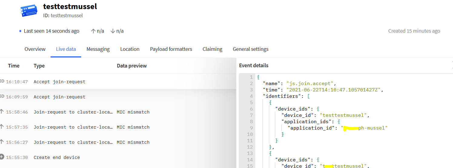
However, now, I am getting a MIC mismatch error:
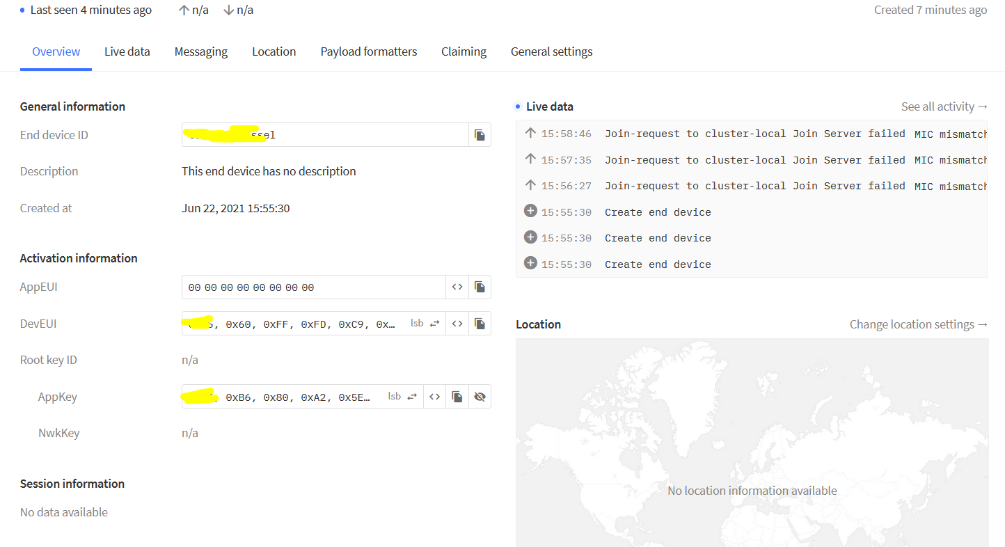
That indicates something with ma AppEUI, AppKEY or DevEUI is wrong, I checked it multiple times. I Generated the DevEUI using the old v2 console. as AppEUI I only took zeroes.
I could add and send reasonable payload using ABP but because there is no option to remove the frame counter check, I cannot really use that option.
What am I doing wrong with the OTAA activation? I used LoRaWAN 1.0.2 protocol as previously, tested PhysA & B.
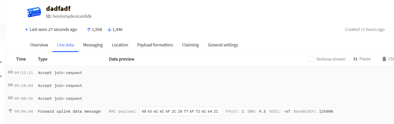
EDIT: when changing the DevEUI from msb to lsb, I receive the following response:
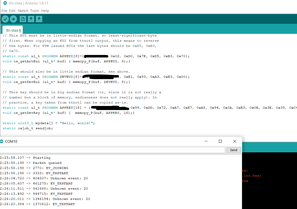
But I don’t get the payload using the standard LMIC-OTAA example:
/*******************************************************************************
 * Copyright (c) 2015 Thomas Telkamp and Matthijs Kooijman
 * Copyright (c) 2018 Terry Moore, MCCI
 *
 * Permission is hereby granted, free of charge, to anyone
 * obtaining a copy of this document and accompanying files,
 * to do whatever they want with them without any restriction,
 * including, but not limited to, copying, modification and redistribution.
 * NO WARRANTY OF ANY KIND IS PROVIDED.
 *
 * This example sends a valid LoRaWAN packet with payload "Hello,
 * world!", using frequency and encryption settings matching those of
 * the The Things Network.
 *
 * This uses OTAA (Over-the-air activation), where where a DevEUI and
 * application key is configured, which are used in an over-the-air
 * activation procedure where a DevAddr and session keys are
 * assigned/generated for use with all further communication.
 *
 * Note: LoRaWAN per sub-band duty-cycle limitation is enforced (1% in
 * g1, 0.1% in g2), but not the TTN fair usage policy (which is probably
 * violated by this sketch when left running for longer)!

 * To use this sketch, first register your application and device with
 * the things network, to set or generate an AppEUI, DevEUI and AppKey.
 * Multiple devices can use the same AppEUI, but each device has its own
 * DevEUI and AppKey.
 *
 * Do not forget to define the radio type correctly in
 * arduino-lmic/project_config/lmic_project_config.h or from your BOARDS.txt.
 *
 *******************************************************************************/

#include <lmic.h>
#include <hal/hal.h>
#include <SPI.h>

//
// For normal use, we require that you edit the sketch to replace FILLMEIN
// with values assigned by the TTN console. However, for regression tests,
// we want to be able to compile these scripts. The regression tests define
// COMPILE_REGRESSION_TEST, and in that case we define FILLMEIN to a non-
// working but innocuous value.
//
#ifdef COMPILE_REGRESSION_TEST
# define FILLMEIN 0
#else
# warning "You must replace the values marked FILLMEIN with real values from the TTN control panel!"
# define FILLMEIN (#dont edit this, edit the lines that use FILLMEIN)
#endif

// This EUI must be in little-endian format, so least-significant-byte
// first. When copying an EUI from ttnctl output, this means to reverse
// the bytes. For TTN issued EUIs the last bytes should be 0xD5, 0xB3,
// 0x70.
static const u1_t PROGMEM APPEUI[8]={0x00, 0x00, 0x00, 0x00, 0x00, 0x00, 0x00, 0x00};
void os_getArtEui (u1_t* buf) { memcpy_P(buf, APPEUI, 8);}

// This should also be in little endian format, see above.
static const u1_t PROGMEM DEVEUI[8]={0xE5, 0x60, 0xFF, XXX};
void os_getDevEui (u1_t* buf) { memcpy_P(buf, DEVEUI, 8);}

// This key should be in big endian format (or, since it is not really a
// number but a block of memory, endianness does not really apply). In
// practice, a key taken from ttnctl can be copied as-is.
static const u1_t PROGMEM APPKEY[16] = {0x22, 0x73, 0xBB, 0xB1, 0x7C, 0x05, XXX};
void os_getDevKey (u1_t* buf) {  memcpy_P(buf, APPKEY, 16);}

static uint8_t mydata[] = "Hello, world!";
static osjob_t sendjob;

// Schedule TX every this many seconds (might become longer due to duty
// cycle limitations).
const unsigned TX_INTERVAL = 10;

// Pin mapping
const lmic_pinmap lmic_pins = {
  .nss = 12,
  .rxtx = LMIC_UNUSED_PIN,
  .rst = 13,
  .dio = {2, 3, 15},
};

void onEvent (ev_t ev) {
    Serial.print(os_getTime());
    Serial.print(": ");
    switch(ev) {
        case EV_SCAN_TIMEOUT:
            Serial.println(F("EV_SCAN_TIMEOUT"));
            break;
        case EV_BEACON_FOUND:
            Serial.println(F("EV_BEACON_FOUND"));
            break;
        case EV_BEACON_MISSED:
            Serial.println(F("EV_BEACON_MISSED"));
            break;
        case EV_BEACON_TRACKED:
            Serial.println(F("EV_BEACON_TRACKED"));
            break;
        case EV_JOINING:
            Serial.println(F("EV_JOINING"));
            break;
        case EV_JOINED:
            Serial.println(F("EV_JOINED"));
            {
              u4_t netid = 0;
              devaddr_t devaddr = 0;
              u1_t nwkKey[16];
              u1_t artKey[16];
              LMIC_getSessionKeys(&netid, &devaddr, nwkKey, artKey);
              Serial.print("netid: ");
              Serial.println(netid, DEC);
              Serial.print("devaddr: ");
              Serial.println(devaddr, HEX);
              Serial.print("artKey: ");
              for (int i=0; i<sizeof(artKey); ++i) {
                Serial.print(artKey[i], HEX);
              }
              Serial.println("");
              Serial.print("nwkKey: ");
              for (int i=0; i<sizeof(nwkKey); ++i) {
                Serial.print(nwkKey[i], HEX);
              }
              Serial.println("");
            }
            // Disable link check validation (automatically enabled
            // during join, but because slow data rates change max TX
	    // size, we don't use it in this example.
            LMIC_setLinkCheckMode(0);
            break;
        /*
        || This event is defined but not used in the code. No
        || point in wasting codespace on it.
        ||
        || case EV_RFU1:
        ||     Serial.println(F("EV_RFU1"));
        ||     break;
        */
        case EV_JOIN_FAILED:
            Serial.println(F("EV_JOIN_FAILED"));
            break;
        case EV_REJOIN_FAILED:
            Serial.println(F("EV_REJOIN_FAILED"));
            break;
        case EV_TXCOMPLETE:
            Serial.println(F("EV_TXCOMPLETE (includes waiting for RX windows)"));
            if (LMIC.txrxFlags & TXRX_ACK)
              Serial.println(F("Received ack"));
            if (LMIC.dataLen) {
              Serial.print(F("Received "));
              Serial.print(LMIC.dataLen);
              Serial.println(F(" bytes of payload"));
            }
            // Schedule next transmission
            os_setTimedCallback(&sendjob, os_getTime()+sec2osticks(TX_INTERVAL), do_send);
            break;
        case EV_LOST_TSYNC:
            Serial.println(F("EV_LOST_TSYNC"));
            break;
        case EV_RESET:
            Serial.println(F("EV_RESET"));
            break;
        case EV_RXCOMPLETE:
            // data received in ping slot
            Serial.println(F("EV_RXCOMPLETE"));
            break;
        case EV_LINK_DEAD:
            Serial.println(F("EV_LINK_DEAD"));
            break;
        case EV_LINK_ALIVE:
            Serial.println(F("EV_LINK_ALIVE"));
            break;
        /*
        || This event is defined but not used in the code. No
        || point in wasting codespace on it.
        ||
        || case EV_SCAN_FOUND:
        ||    Serial.println(F("EV_SCAN_FOUND"));
        ||    break;
        */
        case EV_TXSTART:
            Serial.println(F("EV_TXSTART"));
            break;
        default:
            Serial.print(F("Unknown event: "));
            Serial.println((unsigned) ev);
            break;
    }
}

void do_send(osjob_t* j){
    // Check if there is not a current TX/RX job running
    if (LMIC.opmode & OP_TXRXPEND) {
        Serial.println(F("OP_TXRXPEND, not sending"));
    } else {
        // Prepare upstream data transmission at the next possible time.
        LMIC_setTxData2(1, mydata, sizeof(mydata)-1, 0);
        Serial.println(F("Packet queued"));
    }
    // Next TX is scheduled after TX_COMPLETE event.
}

void setup() {
    Serial.begin(9600);
    Serial.println(F("Starting"));

    #ifdef VCC_ENABLE
    // For Pinoccio Scout boards
    pinMode(VCC_ENABLE, OUTPUT);
    digitalWrite(VCC_ENABLE, HIGH);
    delay(1000);
    #endif

    // LMIC init
    os_init();
    // Reset the MAC state. Session and pending data transfers will be discarded.
    LMIC_reset();

    // Start job (sending automatically starts OTAA too)
    do_send(&sendjob);
}

void loop() {
    os_runloop_once();
}