Hi
I am just wondering if somebody else experienced similar behaviour of a node. Depending on the environment, I had two cases of a node going into a reboot loop while transmitting. In one occasion it helped to tilt the wire helix antenna by about 45° to stop this happening. On the other occasion removing the node (in plastic box) from a corrugated sheet iron roof stopped the strange rebooting.
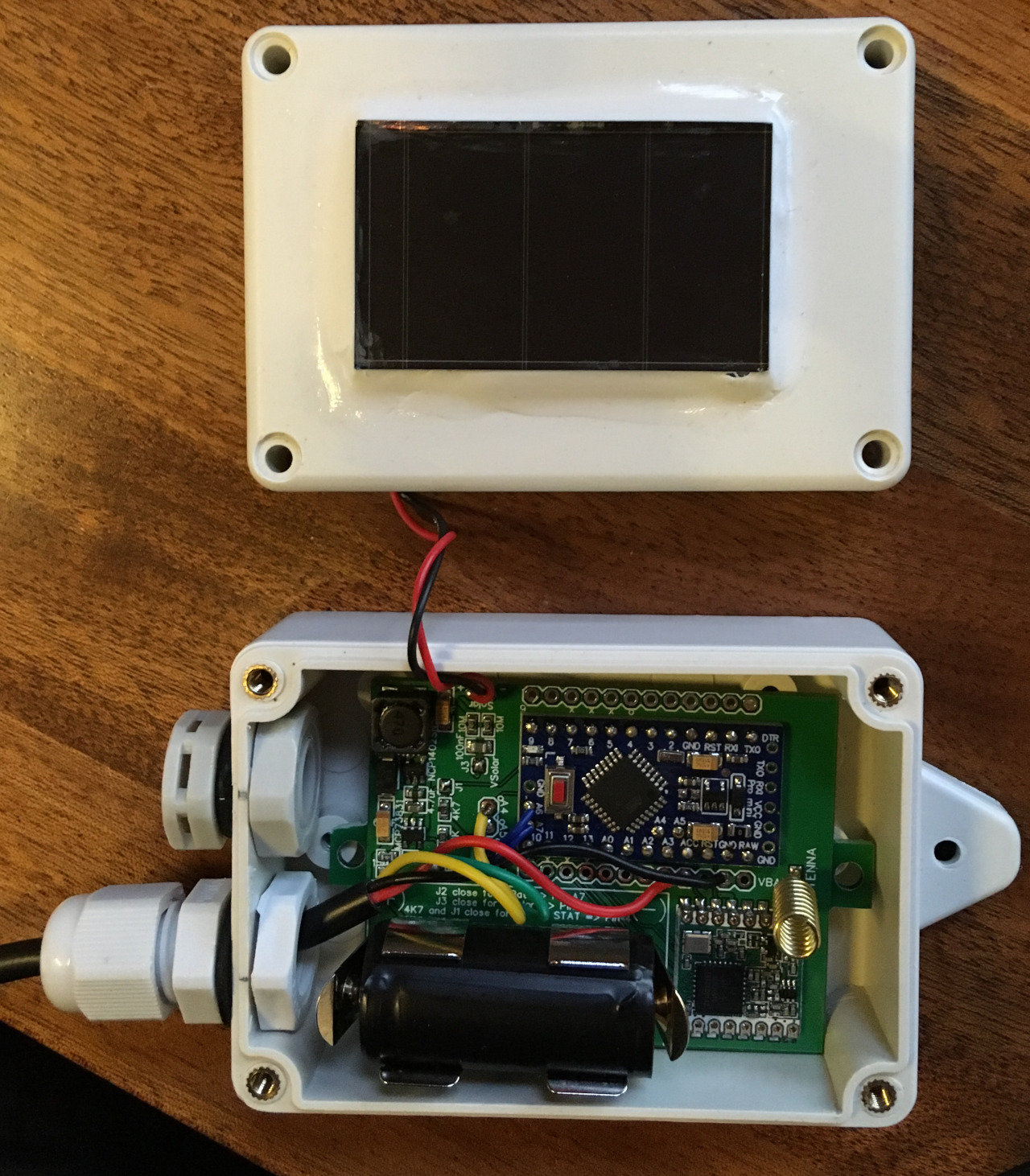
The node is a custom build PCB based on a ATmega328P and a RFM95 with a temperature and humidty sensor attached, a wire helix antenna and solar cells on top of the box.
I am not particularly asking how to fix this from happening as without showing schematics and the PCB nobody knows what I am doing.
It is more that I am wondering if this really is possible. It seems that during transmission some current is induced somewhere causing the Atmega to reset. Very strange…
Without a schematic is just speculation. Area’s I would look at include ability of the 3.3 volt regulator to deliver the required current during transmit. Power supply filtering and decoupling.
This is really unanswerable without details, as it could be anything from a brownout of your power source (some batteries are actually position dependent; different spreading factors would cause different momentary load) to bad software state causing a crash and hopefully restart.
Try getting some serial debug out from your node that endures through the issue: I’ve got a couple nodes scattered around each sitting on a network-linked raspberry pi that continually logs node debug output so I can see what actually happens in realistic situations far from a gateway and so on (I can also use the pi to push new firmware into the node to update the tests being run)
Battery is fine, but I will definitely look „into“ the LDOs capabilities.
What is still perplexing me is the fact that the problem is related to the orientation of the antenna and/or the „electromagnetic“ environment of the node.
And yes, might be caused by different power needs depending on spread factors. I did not think of these, yet. Or there is some electromagnetic interference into my circuit.
Probably it is just some bad PCB design by myself but I find it stunning what seemingly tiny details can keep you busy.
Don’t guess, add debug output to your code, including a message printed on startup, and get something logging this across operation including failures. Look at the last message printed before the startup message, and you’ll start to get some clues.
You could also arm a storage scope to trigger on power rail droop. Or possible even use the ADC on another Arduino to hack up a crude version.
It is difficult, not to guess under these circumstances.
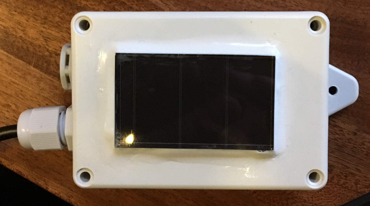
To illustrate, here are two pictures:
Working:
NOT working (rebooting after activation transmission):
See the difference?
The lid is closed. That’s all. No loose wiring etc.
I can also hold my phone or a piece of sheet metal over the antenna in a similar distance as the lid and I will lead to the rebooting cycle. Holding my hand above it, does not cause the effect
I kind of solved it by changing the antenna orientation from perpedicular to the PCB to as parallel as possible. Now it works.
More debugging or root cause analysis would be great, but I do no have the expertise and knowledge and probably also not the instrumentation to deal with RF interferences, especially as the effect is probably not as reproducible as would be needed under measuring conditions.
I have only seen this effect twice, both times with the same PCB series, so I am pretty sure I messed up something in my design and I maybe have got one of the traces at a perfect length to pick up the signal.
For other users, I would leave it with the following hint:
If your node is rebooting and you have no clue why, take into consideration this effect.
Thank you all again for thinking with me and if somebody thinks “wait, I have seen this…” I am curious to learn more.
The is one issue in particular that can cause your problem, and issues with the antenna can indeed make the problem worse or better.
You may not have not cured this particular problem, even though you might think you have, and at some point in the future your node could well reset itself.
However that is speculation based on experience on my part and since you have not provided a schematic, I could not comment further …
Hi @Miwo, the cause could be simple induction from the RF antenna into the unshielded processor chip. When you put the lid on, more of the RF power is being reflected back into the enclosure onto the processor chip causing memory or logic errors.
The distance between the antenna and the chip means that the chip is inside the RF near field so electric currents will be induced in any wires. Same way that your contactless credit/debit card gets powered up without a battery.
For the entertainment of the forum I can reliably cause an unshielded Pycom Lopy4 to reboot at about 20m distance from an electric utility sub-station transformer (33kV down to 11kV).
My advice:
You can use unshielded electronics for dev work but for production it would be best to use a shielded variant that has a grounded metal cap over the chips.
Construct the system so that the antenna has its high-gain direction pointing away from the electronics. Normal external “rubber duck” antenna arrangement.
I agree with Tim’s assessment of the problem. For a possible workaround on your existing hardware, try this:
on the processor, set all unused pins to outputs and set these outputs to zero.
If you are using external interrupts then put a 10 to 100nF on the input.
If you have inputs on the processor and are using internal pull-ups on the processor, then this is not good enough, put pull up low vale (say 3.3K) resistors on these pins and, if practical, also put 10-100nf capacitors from these inputs to ground.
One’s eyes are not electrical test instruments. Nor are they able to see the internal function of MCU software.
The tools you should be using are a storage scope watching the power rail (or else some improvisation like an Ardiono ADC input), and debug output from the MCU firmware run through a recording serial terminal program.
It also looks like you have a switching power supply in there, which in addition to your present reboot problem could be generating noise de-sensitizing your receiver, or in an extreme case corrupting transmissions.
I have seen this type of problem several times, with the Pro Mini resetting when the transmitter is turned on. Changes to the antenna, wiring or shielding and\or waving your hand around etc can make the problem better or worse. The same problem, the resetting, occurs when switching loads such as GPSs that are connected to VCC on the Pro Mini.
The problem can be significantly reduced by changing the brownout level. The brownout level set on every 3.3V Pro Mini I have used in the last 4 years or so has been 2.7V. Thats a bit to close for 3.3V operation and way to close for 3.0V operation. Small short duration spikes on the VCC supply which dont otherwise affect operation can cause the Pro Mini to reset and its not helped by the generally poor supply decoupleing and regulators used.
On every 3.3V Pro Mini I use, I set the fuses for 1.8V brownout and reset problems are then very rare.
It may be best not to use the on-board regulator to power other loads. And for a battery powered project one probably wants to replace it with one having lower quiescent current anyway. Also for old-style FTDI based designs the output current which the on-chip regulator can supply is very limited (though hopefully those are not showing up in a battery-powered context)
But brownout is not necessarily downstream of the regulator, either - many types of batteries will sag under high load, and so the actual input to the regulator can sag far enough to put it into dropout.
With a reduced clock (and there isn’t really any need for a fast one) an ATmega will run at quite low voltages.
Hi, I hope that my approach will help you as it helped me. On the other hand it would be perfect if someone could explain why it works?
I had exactly same issue. When board was out of the enclosure or sometimes when I tried to move the wires inside of the enclosure, it was working. But when I closed the cover it happened that right after the connected to TTN, the board rebooted and all started over. I figured out that it is not during the sending phase but during the receiving phase. Probably something with induction.
I tried several things that I have found on the internet - capacitors between Vcc and Ground of RFM95, on the arduino board. Place pull up resistor to reset pin on the arduino, … And nothing worked.
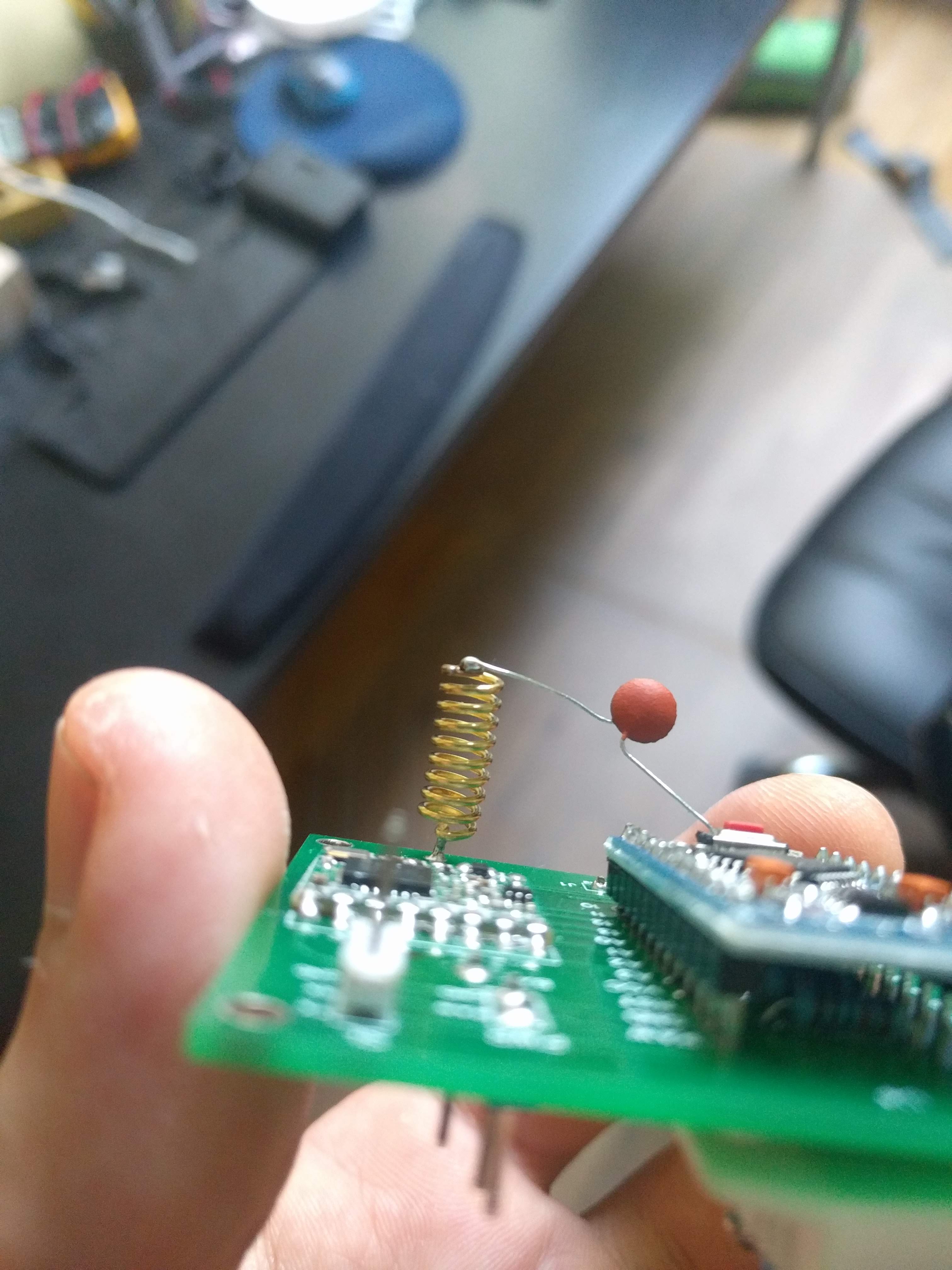
I was so desperate that I was just trying to place the capacitor on different places… And at the end I placed the 104 capacitor (0.1 uF) between the end of the helical antenna and ground. And it just started to work in all places I tried - Inside the enclosure, outside enclosure and in any position I tried. And I did not found any issue with worse signal strength (from the TTN console).
I think that I made a filter but don’t know what filter it is. The upper pass or lower pass filters are normally made of a capacitor and a resistor. Here, only a capacitor and on very strange place is used.
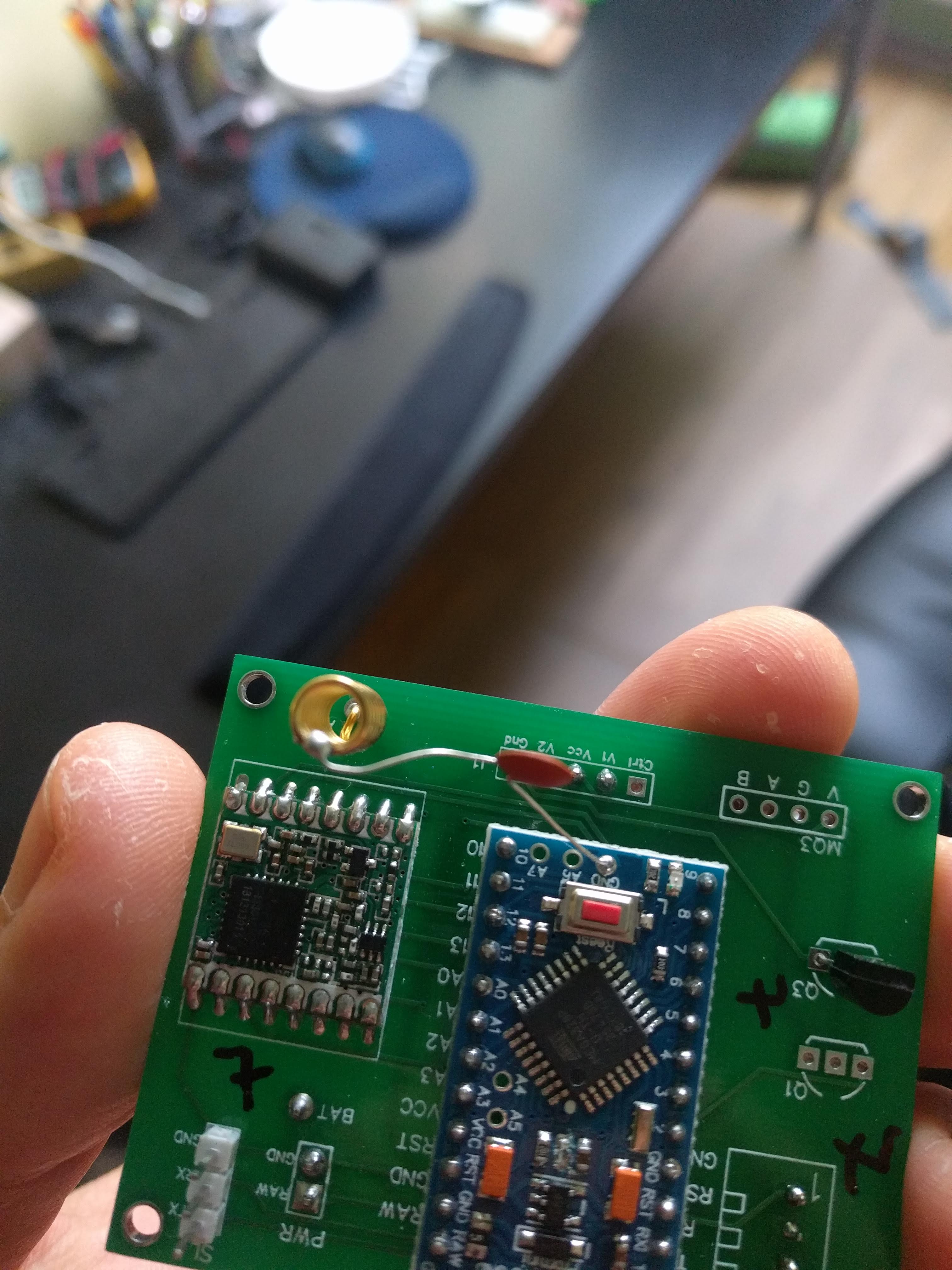
I am uploading pictures with my board. I know it is a nasty hack, but works. If someone can explain what the hell is that, then we might to find a proper solution.
Can you, verify, whether it works on your board as well? According to your photos, the antenna and GND pind on arduino is not far so capacitor can be used exactly as in my case
So far it is deployed on 15 boards that are working fine for several weeks so far. I would like an explanation from someone who knows why it is working.
The messages like “you’re going to destroy everything” are fine, but it will not help me anything.
I think that if there someone who understand the problematic, we can find a proper solution for this. In case @Miwo can try the same approach, maybe he can tell you whether it works as well on his side…
Unless you are sure you know the characteristic impedance of a particular type of 0.1uF decoupling capacitor at the frequency involved, then indeed you, or others, could be indeed be "going to destroy everything”. Ceramic capacitors vary considerably in the dielectric type used and characteristics at RF. Attaching random capacitors to the end of an antenna is not recommended, unless you know its impedance.
As a minimum you would be needing to use some form of antenna tester to see how much the capacitor has messed up or changed the antenna tuning.
A more constructive elimination test would be to check and set the brownout voltage for the Pro Mini. If you have a bad antenna (and those coil things are often not good) then you can get large amounts of reflected power back onto the VCC of the Pro Mini, which can trigger a brownout reset.
I do not mind too much, risking my node (or the node’s RFM95) by attaching a capacitor to the end of the antenna, so I am considering to do it, especially as I already played with wires of different length attached as a replacement for the antenna and noticed that this had a significant impact on the behaviour of my node.
Testing will be a little bit unprofessional, though, as the reproducibility of the effects observed are limited and I do not know of measurements I could really perform except from reporting the effect and maybe some RSSI and S/N values.
And as mentioned before, I am an absolute dummy regarding antenna design and RF behaviour which is why my initial question was: “Has anyone seen this strange type of behaviour (rebooting during/after sending)”. Now, I know the answer is yes. @LuckyV: Thank you for “admitting” and by the way: It is probably rebooting during receive as well here as I see the activate message on the gateway but no answer. I have not been sufficiently precise before regarding this detail.
I must also admit that I have no means (technical/knowledge) to do an assessment of impedances and antenna effects, whatsoever. Even measuring ultra short drops in the voltage for the Pro Mini which might cause brown-outs are - missing a real memory oscilloscope - out of scope for me - Yes, I could attach another Arduino as such.
It, however, sounds reasonable to reduce the brown-out value to something lower, taking care that it does not affect the functionality of the Pro Mini or any of the sensors attached.
What I do not understand is this:
How does the power from the antenna reflect onto VCC? How are the internal connections in the RFM95 causing reflection to induce something back on VCC? Couldn’t it as well induce voltage to GND, thus lowering VCC by this amount comparatively and so causing a brownout?
At least, as far as I understood, you can destroy the RFM module by not having attached an antenna due to reflection at the open pin, although this piece of hardware seems quite robust to me.
I will update here if I know more.
@Miwo, good to know that I am not the only one. My symptoms looks exactly same as yours.
I am dummy as well and in simmilar situation - no oscilloscope and so on.
Maybe there could be made any low pass / high pass filter on the antenna pin to only accept the frequencies somewhere near 868 MHz. Somehow I think that the capacitor does something like that. But, thinking is too far from knowing…
Regarding this, I was trying to attach electrolytic capacitor between GND anv Vcc of Arduino to hold the voltage in case there is any spike when receiving. But maybe the capacitor was still too small or I don’t know - simply there was no change and restarts was still there.
So far I have to use my capacitor-on-antenna solution until someone finds a better one