I have posted the following quote on RAK forum but no one are able to help me:
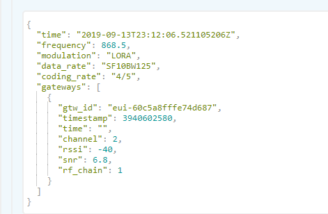
I’m have my RAK7258 868 mHz configuratend in TTN but I’m having some problems with range to comunicate with my 2 BSF LORA32u4 II. I have just the node about 3 meters from gatway with line of sight and I’m getting values of SF10W125, RSSI: -32 and SNR: 9.
The RSSI shouldn’t be lower for this distance?
I made some tests outside, and without line of sight I’m only able to comunicate with my gateway for a distance of about 40 meter.
I am quite disappointed with the results. In the past I made some tests with 2 ESP32 Heltec Lora 433 mHz and I was able to comunicate within a range of 300 meters withouy line of sight.
In RAK7258 I’m using the antenna that cames with it and for BSF LORA32u4 II I’m using na antenna with 19,5 mm with 5bB gain.
Can anyone give me some suggestions about things to check to help solve this?
I’m no sure if it’s a problem with antennas, or with my 2 nodes 32u4 or with my gatway…
I’m considering to buy a better antenna for the gatway but is becoming dificult to put more money in this…
I’m using OTAA activation, should I test for ABP?
Can someone help me with this?
Today I tested with a different board (TTGO LORA32) and I’m having the same results.
Do you think that his may be a problem with my router?
Without anything to make a direct comparison to, this kind of thing is hard to debug.
Typically, you’d put two different nodes next to each other, and two different gateways next to each other, and have something to compare.
I guess you could temporarily rig up a single-channel gateway with one of your nodes to get a signal comparison.
There’s not much to the RAK2758 - you could open up the lid and make sure the antenna cable is actually connected to the concentrator card.
Also make sure all of your gear is actually for the frequency you are using it on! The chips have no way of knowing if the circuitry around them is for 868 or 915, and telling one to operate on the band that circuitry was not designed for would appear to work, but probably perform quite poorly.
Power supply noise is another possibly culprit, LoRa is more resistance than older modulation types, but it’s still worth ruling out. Try a different power supply for the gateway. Run the nodes on batteries with no other wires attached.
It’s not entirely clear if your problem is with the uplink (node to gateway) or downlink (gateway to node) path or both. The more you can figure out the more help you are likely to be able to get.
Hi The value of around -30dB at a few cm is normal. The question what is the Rossi at 40m. I would always question the antennas as they are often not good on the frequency used. Do yo have ability to test the antennas ?. In tests I did 40% of them did not work and the rest I had need to be tuned. You state the antenna was 5 dBi that would be typically 60-70 cm long 3dBi about 35cm and a plastic whip about 2dBi at best. Cables can also cause problems so should be tested. Most Chinese antennas vert over stated spec and also you need to know the radiation pattern as you may be in s null.I have generally found not general fault with gateways or node but more how they are used, hence the need for spectrum and antenna test kit. Simon
I will try to use my TTGO LORA as a single channel gateway and I will try to test the RAK gateway with a different power supply.
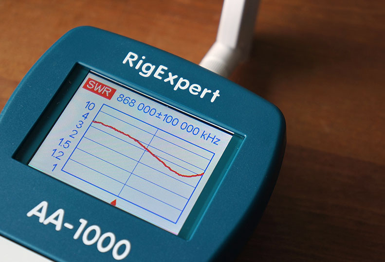
Hi Vaelid, I don’t have the possibility to test my antennas, I saw the video of Andreas Spiess about N1201SA, but to be honest it’s hard to me put more money with such disapoint results…
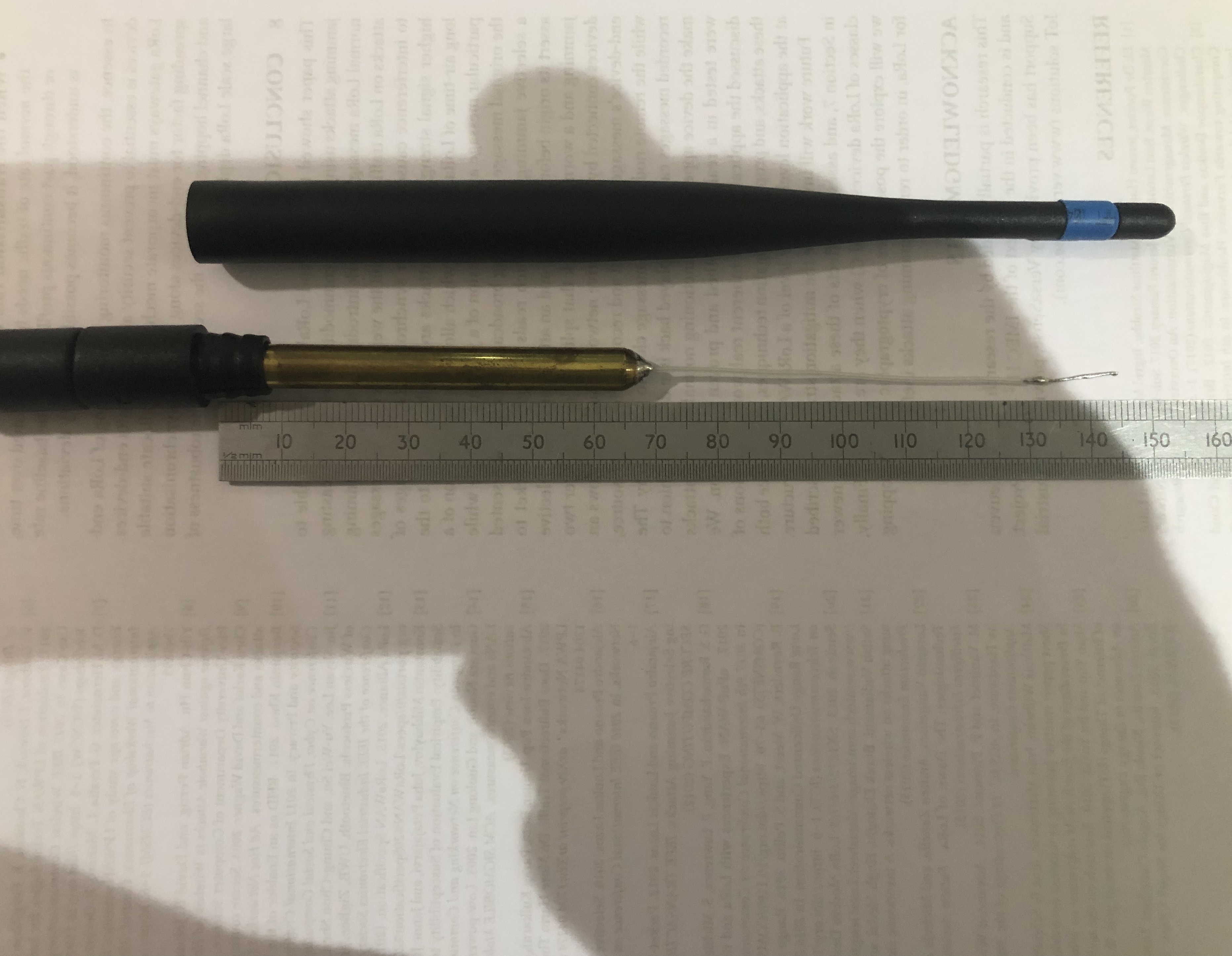
This is the antenna that I use for my LORA32u4 nodes:
I would first check with another indoor antenna and your node shouldn’t be within 10 meters of your gateway.
Maybe switch antennas node-gateway (if that fits?)
A second range test could be to place an antenna outdoors, connected with a cable.
If you don’t want to buy now you can build a beter one yourself
FWIW I put a US915 RAK2758 in between two RAK833 + SBC custom gateways and wrote a quick program to plot list signal strength for multiply received packets with a column per gateway I’m not seeing any consistent difference, there is variation in each packet (including cases of gateways missing it entirely) but no consistent winner.
(Something that is a little interesting is that the uniquely missed packets seem a little bursty for each gateway. These were running on a private network where one shoulders a heavy majority of frequent transmit tasks - a difference not apparent in the reception - but I may modify my analysis a little to try to add when they are talking…)
Or course the RAK2247 in the RAK2758 box is pretty much just a respin of the RAK833, introducing a undesirable level translator but probably not changing the RF section much.
Anyway my example of the RAK2258 doesn’t seem to be an outlier.
I suspect the OP either has an issue with the setup, or something uniquely wrong with an individual gateway.
Hi to help with the antenna shown.It will be about 3dBi. They make 10000’s of these and try to make them do many markets 915mhz, GSM 868 MHz etc. You will probably find if you gently pull off the cover that inside there is a large dia tube with a smaller one soldered on to and coax outer soldered to it . This smaller tube needs to be removed and the coax soldered to the top of the tube. The lengh of the coax iner and a bit of wire soldered to the top needs to be 76mm. This will tune better at 868mhz for you. See picture I have enclosed. Have fun Simon.
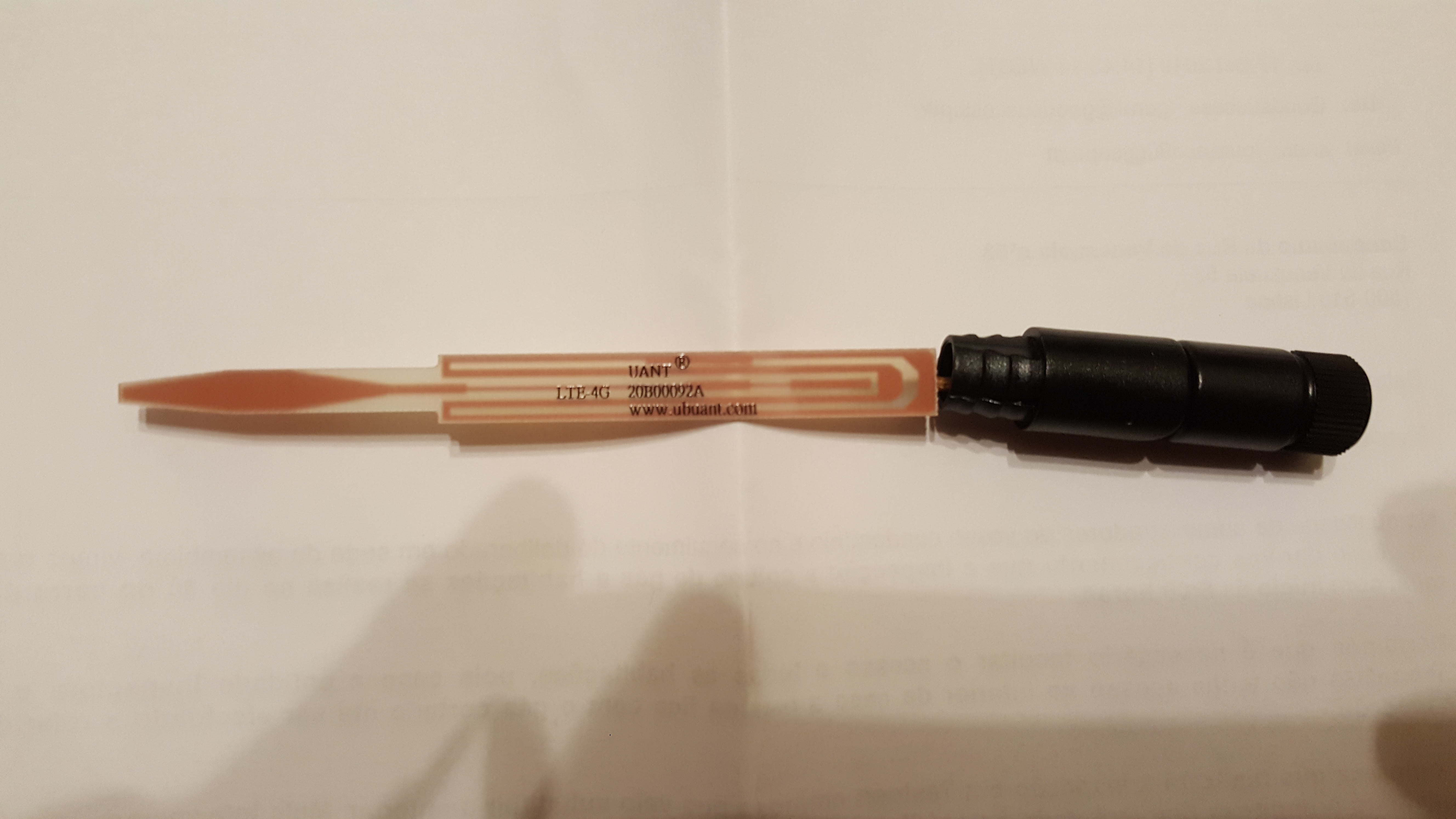
Hi ok yes it’s a printed circuit board and not an antenna designed for 868mhz . It states LTE and 4g not the ISM band.its design is broad band so little gain probably a loss. For info this is a balun dipole. The part near the connector is the balun and the part at the top is the other half of the dipole . The length of this sets the frequency about 0.9 wavelength /4 . I am sorry but you nead a better tuned antenna like the diy one link above.
Myself, I think everyone involved in TTN absolutly must have a reference antenna that they can use to check their Gateway or Node antennas are actually working properly.
There are more complex antenna designs, such as the co-linear but you really do need an antenna tuner to build them right. The simple 1/4 wave vertical with radials is easy to build and quite hard to build wrong, its an ideal reference point.
Checking an antenna on a tuner can be helpful, but that check wont tell you how well the antenna actually performs when its on a node or Gateway.
With a built GP antenna as a reference you can quickly compare the performance of a ‘suspect’ antenna versus your standard, by checking the RSSI levels of the received packets. Dont compare antennas with only a few meters between node and Gateway, but 50m+ or so is fine. Make sure node and Gateway stay in the exact same positions and orientation, just swap antennas on the node and check out the RSSIs. You can check Gateway antennas like this also, just swap the node antenna between GP reference and the proposed Gateway one. Make sure you do not operate Gateway or node without an antenna connected.
The GP antenna shown above has as much gain that is legal to use (in most cases) so why beat yourself up building a higher gain antenna thats not legal to use ?
My personal take on that is simply go out and measure the performance on the field. RF is chaotic, terrain characteristics and nearby structures could affect your result. Even if you are using the exact same hardware it would give you a different result. (Unless you have an FCC-testing-grade anechoic chamber)
I agree that low-distance tests are not going to give you a very good idea about the performance.
In my case I have achieved almost 10Km LoS coverage with a simple 1/4 wavelength monopole wire antenna cut by hand.
What we do here is to simulate the coverage first to have a rough idea about the coverage we could get. We use SPLAT for that task, however it requires to know the characteristics of the antennas. And later we go to the field and test if it works as the model indicates. At least with locations in LoS it works, with buildings and obstacles the performance is simply unpredictable and you must measure it.
Seems to me you’re sensor is ‘shouting’ at the GW’s ‘ear’ because they’re too close, this is called Rx desensitization. -30’s dBm is actually not a good RF level to operate and the high SF is letting you know. The exact level of course will depend on the GW max input range. But rule of thumb you shouldn’t be ‘hotter’ than -45 dBm- ish, again depending on mfr spec. Remember, more is not always better. Another thing I don’t think is an issue is noise/interference as you’re getting good SNR, almost 10 times over the noise. Something else is going on here. First, separate physically that sensor away from the GW until you get into the -40’s to -50’s dBm RSSI. Then check again. Your SNR should stay the same or improve, your SF should get lower and your msgs should go thru unless something else is wrong, as some have stated above. Until you figure what is it, don’t add any more gain to the antenna as you’ll shout even louder at this distance. Check your sensor output power as well.
Using the RSSI from the Gateway to check and compare antennas is not ideal as the Gateway may not be in a convienient location either.
I dont have ready access to a ‘FCC-testing-grade anechoic chamber’ and I doubt most TTN users do either.
So if I want to test or compare antennas then I do it over the local park, a nice sunny day is best, all you need is a couple of simple Arduino boards, technique described here;
While I’m waiting for some N-style chassis to build my antennas.
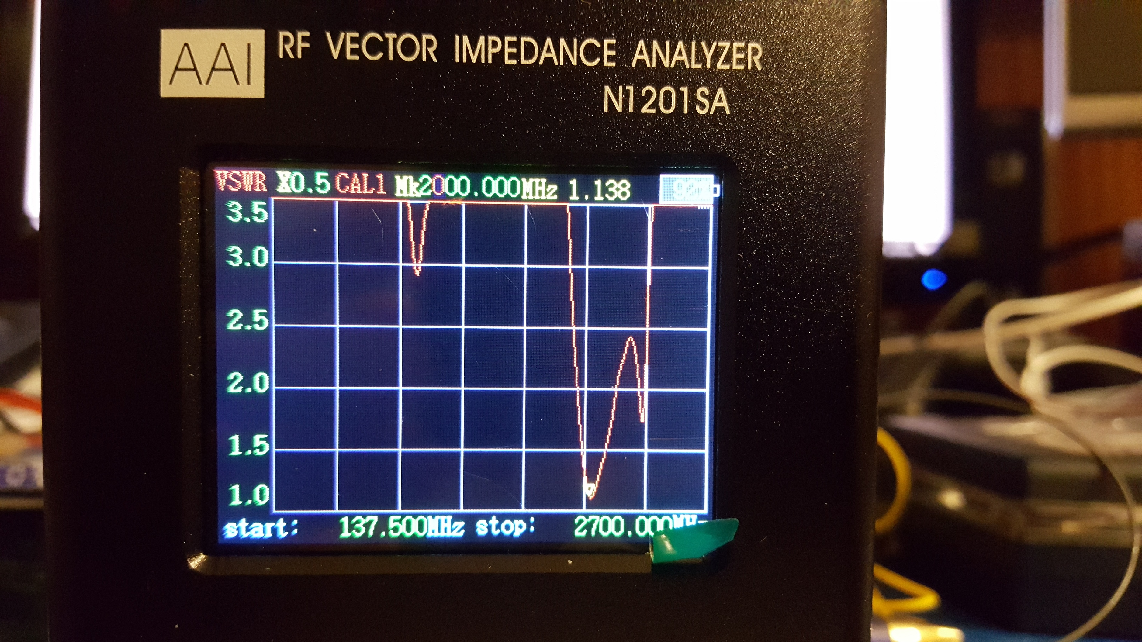
I also ordered the N1201SA…
Here is a picture of one 868MHz antenna that I bought on ebay: