DIY external antenna for gateway

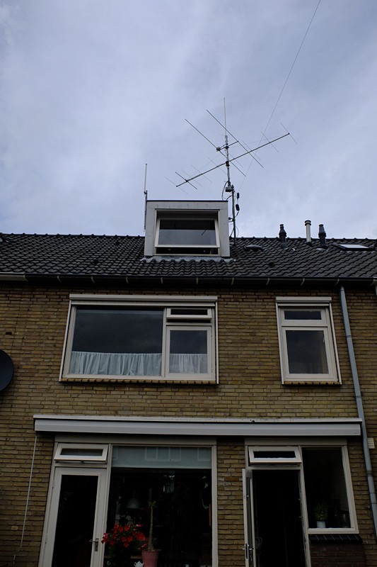
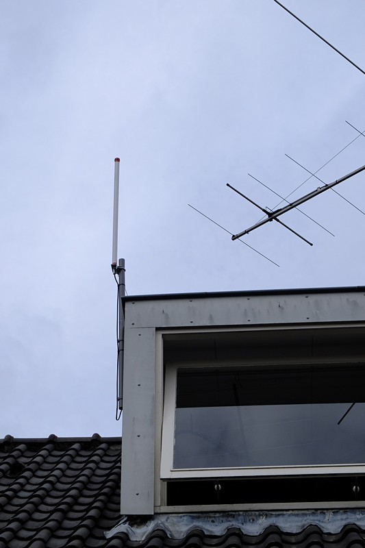
Because I didn’t like to have a indoor antenna on my LoRA gateway and I wanted to expande the range of it, I desided to make a simple 6dBi Collinear Antenna as build for 2.4Ghz by MartyBugs. It’s a simple non-nonsens design which has proven in time.

I calculated the dimensions for 868Mhz and the sketches can be found below.

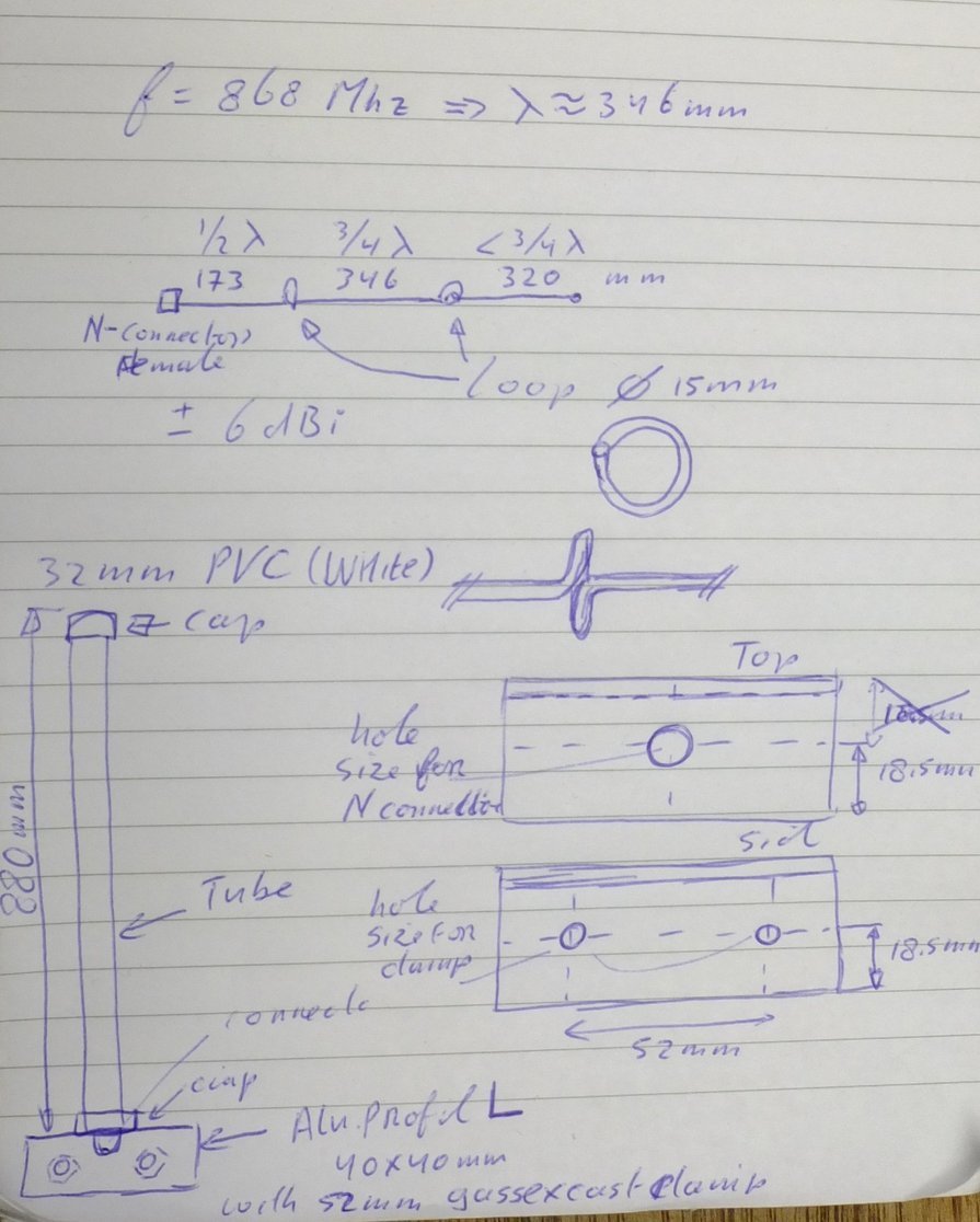
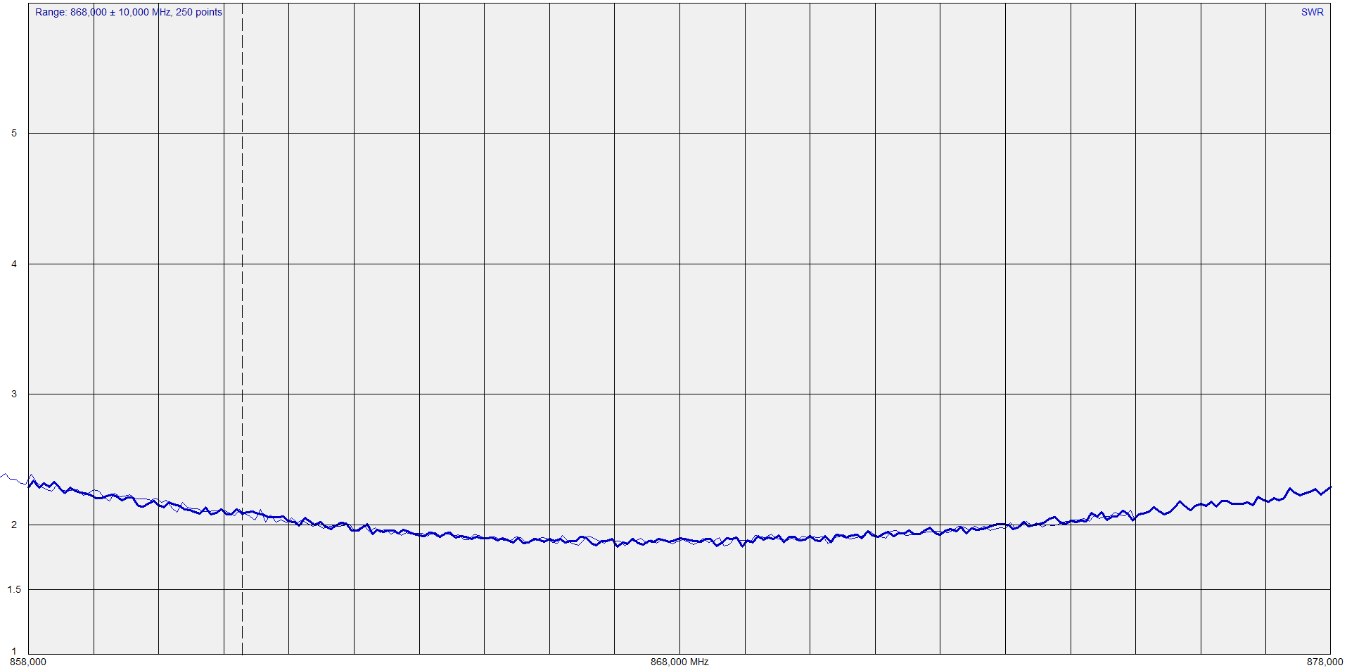
After the inital building and tweaking I took the antenna to my local Hamradio club (Veron/VRZA Twente) to have it tested with a RigExpert AA-600 (which when connected to the computer can work up to 1.4Ghz) from a fellow Ham. Some minor tweaking (adding 2 cm to the top section) the SWR dip was right on the 868Mhz.

I forgot to make pictures of the build, so I took it apart again to make some.

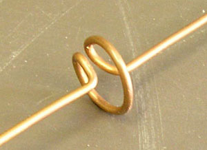
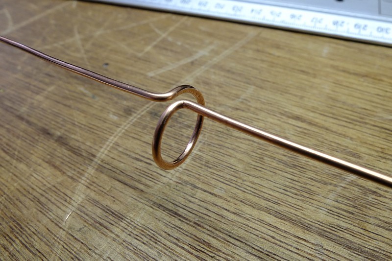
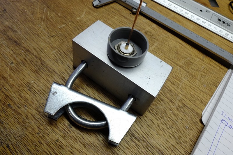
Close-up from the loop. Remember both have to have the same direction.

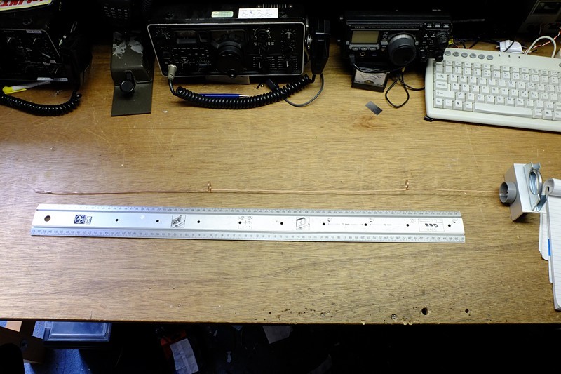
The wire and the back-side from the N chassis part. and the 32mm PVC end-cap.

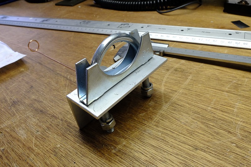
The 52mm car exhaust clamp

other side

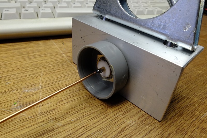
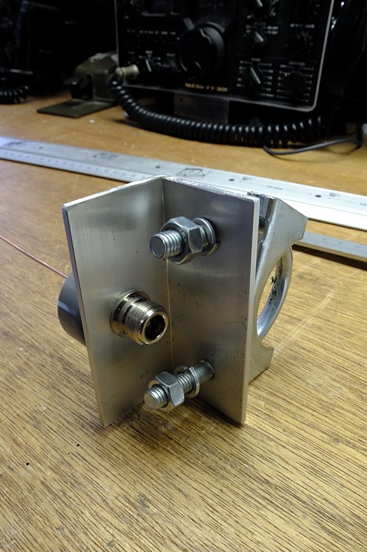
The front side from the N chassis part.

Boxing it all up again.

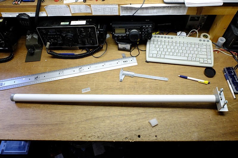
After that, everything was put together again for the final indoor test (it was raining cats and dogs so the installation outdoor will have to wait a day).

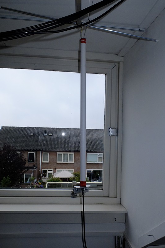
The first result are very promissing. With a testnode I transmitted a series of messages from the same location. With the indoor antenna I got a average RSSI of -65 with the indoor antenna (Gateway setup in the window) to a average RSSI -49 (even got one -44) with the new outdoor antenna (in the window).

But the prove is in the pudding, so that evening I did the test again.

New test run with the Lorank8 gateway with the original indoor antenna.

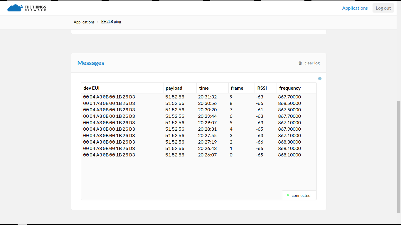
Average RSSI : -64.1

New test run with the Lorank8 gateway with the new outdoor antenna (used indoor on same location).

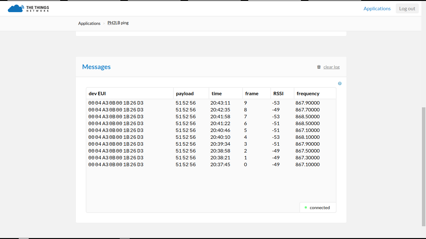
Average RSSI : -50.8

Hmmmm not the average I got this afternoon. Maybe there is more interference in the evening on the 868Mhz (it’s a shared ISM band so maybe there are headphones and babyphones up and running). But then again, RSSI from -64.1 up to -50.8 and that’s a good improvement.

Any comments or questions, drop a comment :smile:

12 Likes

Nice post, i got 2 questions:

  1. how many cable can you run from the GW to the antenna, and how would it effect the RSSI? I want to place an antenna outdoors as i am in a very flat area thus could add a lot of extra coverage by putting it outdoors.

  2. for the not so handy people among us,is there a place were we can just buy such an antenna? (and cables, what kind?)

thnx

Impressive work you did there @lex_ph2lb!

It would be great if you could create a tutorial for this on The Things Network Labs. Please let me know if you need any help with doing so.

1 Like

Hello Kruisdraad,

thank you for you’re questions.

(1) The length of the cable does effect the RSSI.

For example, the cable I use is the AirCell 7 which has Typ. attenuation (dB/100m@20°C) of 19.0 dB for a frequency 800 Mhz and 21.52 dB for a frequency of 1000Mhz.
(see : http://www.paratronic.fi/dokumentit/DB-Aircell7-UK-SF.pdf ) For 868 Mhz this will be result in a attenuation of aprx. 20 dB for 100m cable length (so the RSSI would affected with -20dB when a cable of 100m would be used). This is off-course non-realistic. But for my outdoor antenne I would use a cable with a length of 6m . That would result in a attenuation of aprx. 1.2 dB. So with that cable the RSSI would decrease with -1.2 when using the same antenna on the same location. against the antenna directly mounted to the gateway. For example when a node is received with a RSSI average of -64 with a direct connected antenna to the gateway, the node will be received with a RSSI average of -65.2 when the antenna is connected by the cable to the gateway (but with antenna on the same position).

Because we want to use a outdoor antenna with a gain of 6dBi. That antenne with cable would increase the RSSI from -64 - 1.2 + 6 = -59.2 Still a nice 6 - 1.2 = 4.8 dB gain over the stock antenna (assuming its cheap and has 0 dB gain). Placing it outside in clear view would remove the indoor attenuation (all materials between the node and the gateway will add attenuation) so the RSSI would be even better.

When using a cheaper but more common used consumer cable like the RG-58 with a attenuation of 70 dB for a length of 100m. A cable with a length of 6m would result in a attenuation of almost 4.2 dB. It sounds like much even with LoRaWAN who has a good signal to noise ratio a RG-58 could work out. But remember cutting 4.2 dB on the cable and gaining 6 dB on the antenne would result in a overall gain of just 1.8 dB.

But remember : Placing the antenne outdoor in a clear view would really expand the range of the gateway. IMHO, invest a little in quality. For example in Aircell 7 cables with quality connectors (or other low loss cable) and it will pay off. The most low-loss cables are most of the time professional stuff and the N type connectors are water proof (with outdoor antennes I always use N type connectors).

(2) I have seen external 868Mhz antennes on eBay, Conrad and Amazon. For that there is a topic on this forum for bargains. The BARGAIN basement part 1 . Scroll down and you find a 6dBi version (the same as my design) for aprx euro 35,00.

Hope the above information helps.

1 Like

Hello Laurens,

Thanks for the pointer. Then I could write a multi step story about it. I will take a look a some stories to get the idea on how to write them. Let me work out a story line for that (introduction and steps) offline and do some redrawing.

One small question : would you place it under The Things or Physical Network (or both)?

Great! Physical network would be best suitable to place it under.

Just for some more details here:

An AirCell cable would be fine and i wouldn’t think about running more then 10m cable with it (or no effect with a 25m cable?) Any idea where to order it and what connectors i’d need for the gateway/antenna sides?

This way i can preorder the stuff and have them when the gateway arrive. I’d imagine that more people are interested in this. I need enough for 4 gateways.

For an outdoor antenna you would typically use an N-connector (also mentioned above). Gateways typically use SMA connectors, although this has yet to be confirmed by @tweetonig for the TTN gateway. The antenna side is typically male for both connectors on the antenna.

I have to agree with @Batilan, N-connectors are indeed the “standard” for UHF and SHF outdoor antenna’s. And my Lorank8 has a SMA connector.

@kruisdraad : Where to buy the cables and connectors, depends on where you live. For example in the Netherlands you can buy cables and connectors at http://www.coaxshop.nl/ or http://www.hogttelecom.nl/. The last has a service where you can let them make the cables for you. But I can’t tell you what the price for a cable would be (but you can contact them and ask them).

Maybe there are community members near you who can help you (can’t find out where you live in you’re profile).

I am also from the netherlands

the cables i’ve seen indeed, but then i need to figure out which connectors i need and need some assembly, but doable.

The antenna’s i can’t find in a NL webshop, unless paying more then double then the bargain prices (quality bad?)

Then there was time to install the antenna outdoor. I thought I could replace a old MiniWhip antenna of my but that locations was blocked in one direction with my main hamradio antenna mast (I have been using the MiniWhip for SWL listening for ages). So I had to find a new spot.And with a bit of labor, sweat, a touch of “Geveltoeristme”, and drilling a hole to get the antenna cable in the shack (the Dormer has a 15cm thick wall), the LoRaWAN antenna was installed on the left side of the dormer.

I can’t raise it that high because it will cross paths with my 2m 9elm Yagi and I’m sure the Yagi will win. But for now it will do (maybe in the future I find al better spot on a higher building).

And there it is.

The results

Well that depends on what you want. Offcourse there is more coverage then with the original indoor antenna. And on some points even better then when I tested the outdoor antenna hanging it in the window of the dormer. But having it raised above a zinc roofing it will have a slight negative effects when the nodes are in the right of the outdoor antenna (especialy when near).

My daughter volunteert to help with a field test. I asked her to make 3 measurements on several locations so I could log the RSSI. I have plotted the results in a MyGoogleMap which can be accesed on this link.

Overall the antenne works well outdoor and most locations have a RSSI of atleast 2 points better and we found a max of 17 points (Sample Point 5). Indicating it all depends on the surrounding area (reinforced concrete, solar pannels on roofs etc) .

To our big supprise we found out that the Node could be spot from my parents house location (Sample Point 7) with a RSSI of -115. Something that wasn’t possible before.

@laurens.slats, Labs story is written and published :

https://www.thethingsnetwork.org/labs/story/homemade-outdoor-868mhz-antenna

When you have any comments please let me know.

1 Like

You mention using a microwave to test for RF absorption. Could you explain the procedure?

@kersing To test materials for RF absorption, put a piece of it on a plate (which of-course should be microwave save) and start with 30 seconds of full power. Check if it becomes warm (safety first). If not try 1 minute. If still not warm, it doesn’t absorb RF and is save to be used for example when building antennes.

Some gray PVC pipes and materials contain carbon in it, which will reflect or absorb RF. When so it will get warm.

The above should never been done with materials which contains metals like CD, CD-ROMS, wire, connectors, coax cables etc.

Disclaimer : use the above information for you’re own risk.

3 Likes

Great story, thanks for sharing.

I’ll contact you later if I have any comments.

Very nice work.Looks similar as http://martybugs.net/wireless/collinear.cgi

rob oudendijk

1 Like

…which also explains:

Testing

When building my first collinear using this design, I made the loops in a similar way to those seen on many commercial antennas which have multi-loop coils, with the wire above and below the coil being centrally located with regards to the loop.

how NOT to do the loops / first attempt at the loops

However, after doing some further research, I realised this was incorrect, and made another collinear using the loops as per the approach described above.

Some quick comparison testing indicates the collinear with the offset loops performs much better than the collinear with the centered loops.

1 Like

That’s indeed the design I referenced (but for some reason the link dropt out the first posting)
Fixed it. Thanks for pointing me out. :smile:

Thanks for post !
Are you check antenna with more loops ?
As at the end of MartyBugs post .

@x893 : Adding more 3/4 Lamba sections will indeed increase the gain but also will flattern the radiation pattern. It may result in communication problems for more near by nodes. Especially when the antenna is positioned high. A example of a high gain omni antenna radiation pattern is shown here : link Notice the lobs from left to right and less on the top and bottom. Also you would have to add 2 x 346mm sections to it having aditional 70cm length to the antenna, making it more wind sensitive (you would need to redesign the base plate for 2 clamps to prevent tilting of the antenna).

But when you have the antenna on ground level (in a near flat environment) it would be great of course to have 2dB aditional gain.