See my post wrt the tracker in Workbench thread referenced earlier - I saw same issue wrt GPS - close to window but still indoors - once I placed in large conservatory with wide view of sky or use outside in open areas the GPS behaves as expected.
Had/have same issue wrt battery life (using 1200mA or 800/900mA batteries and only get decent run times when I use preference config after reset to back off both the app update and gps update times…getting days of run-time.
Payload is Cayenne LPP so integration is easy - eventually as the various functions TX their respective payloads - temp/Humidity/GPS/barometric pressure/Accelerometer/battery level you should see dashboard elements gradually populate…the battery level should come through as an analog value - just change the label in settings to battery/charge level If you are not seeing that come through check if you see it in the TTN console - look at you application data for the device - you should see all the different elements coming though…
Glad that worked
Grab the 5205 WisTrio user manual fro the RAK docs site and look to the configuration commands. If you have a serial (via usb port) terminal open then immediately after board reset and self initialisation <messages will appear setting region, initialising teh MEMS devices etc.> you will see message that it is ready to configure preferences…you have a short time then before it starts full operation & join process etc and fixes operating modes during which you can use at commands to set parameters e.g. at_app_interval: etc. Settings then survive following board resets & cold boots…
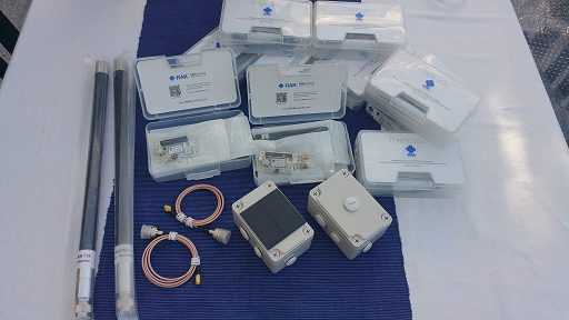
I openned a request at RAK support and they ask me to take a picture of GPS Internal antenna. I think that they have a suspect of a problem at antenna. In this prototype board sometimes they find a problem and then they change. Well this is the price of “agile method”
Next batch of 5205’s just arrived…mix of SMA & iPX, along with samples of the new housings for test - with & without Solar panel…competition for the ‘Nut’ tins!
Did somebody try to measure the power consumption?
I am not able to reach the 15uA mentionned in the datasheet using the stock firmware (2.0.0.6)
The sleep current I measure with the nordic power profiler kit is around 1.5mA
Any feedback regarding the power consumption? Using a 3200mAh LiPo battery, the node is able to work for a week or 2 sending data every 15 minutes using the firmware from RAK
Hello everyone I just connect my 5205 tracker update the firmware (fw RAK811_HF_trackerboard_V2.0.1.9.bin) and perform the otaa process to connect the device to TheThingsNetwork but the association failed (Join Failed!).
In my application I receive the data from dev addr and app eui, only that.
I saw some comments about the fw and the violation of the time of use of the air. Therefore, I would like to know or recommend me which fw to use or how to modify the time of sending messages.
I have little knowledge about the RAK5205 but reading about that it does not reach its advertised sleep mode power consumption the following could play a role:
Are all sensors (e.g. BME680) and peripherals (e.g. GPS) properly configured to use the least power before the MCU enters deep sleep?
If not, they may draw significantly more power (assuming they stay connected to power when the MCU is in sleep mode) then when properly configured for least power use.
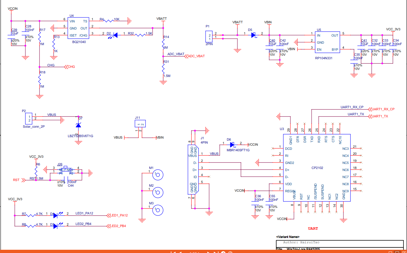
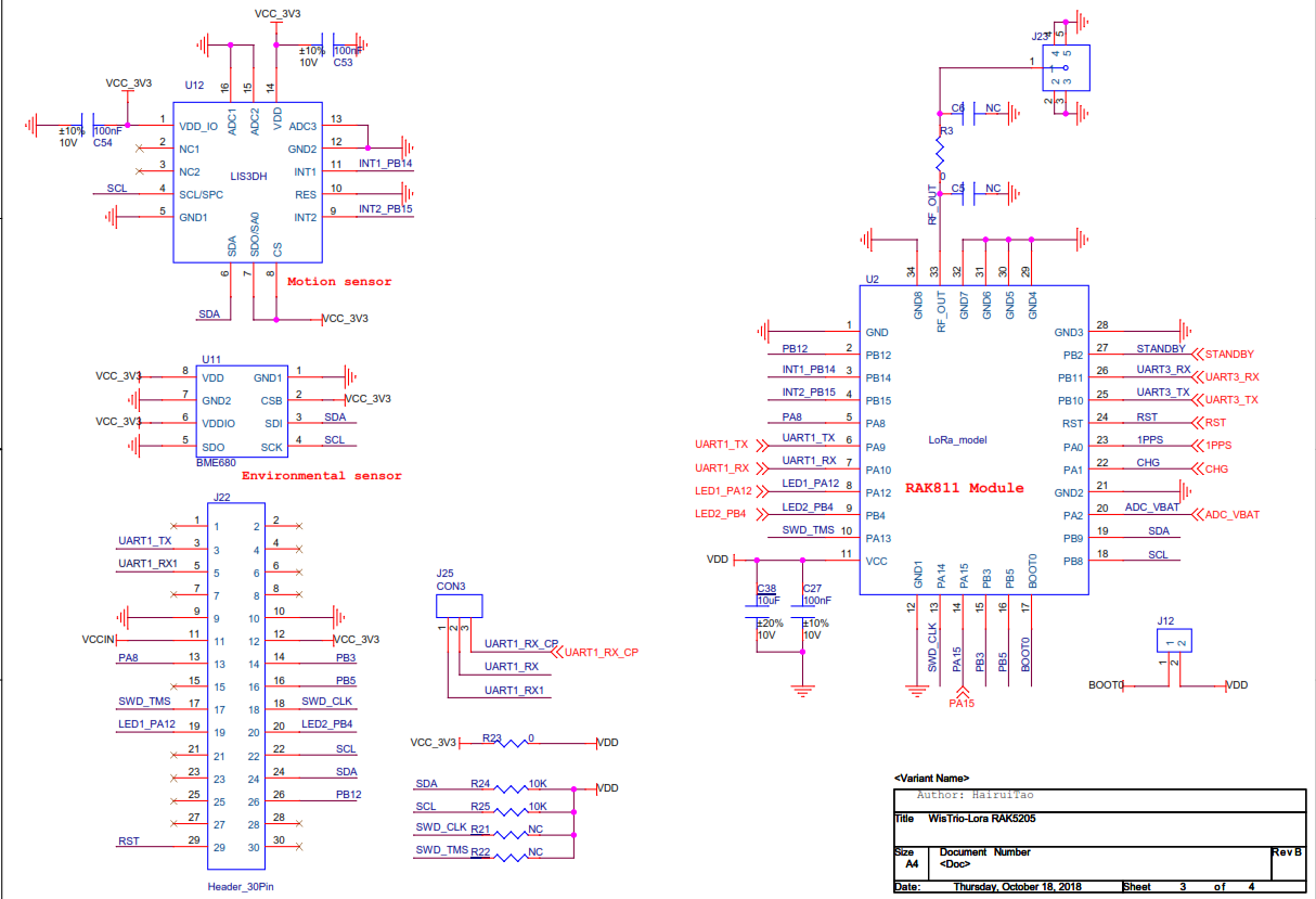
Is a circuit diagram of the board available? A circuit diagram would allow to check if the advertised low-power/deep sleep current is possible at all, from hardware perspective.
Above linked topic on RAK forum mentions a measured low-power/sleep mode current for the board of 1.5mA while the advertised low power current is 14.5uA.
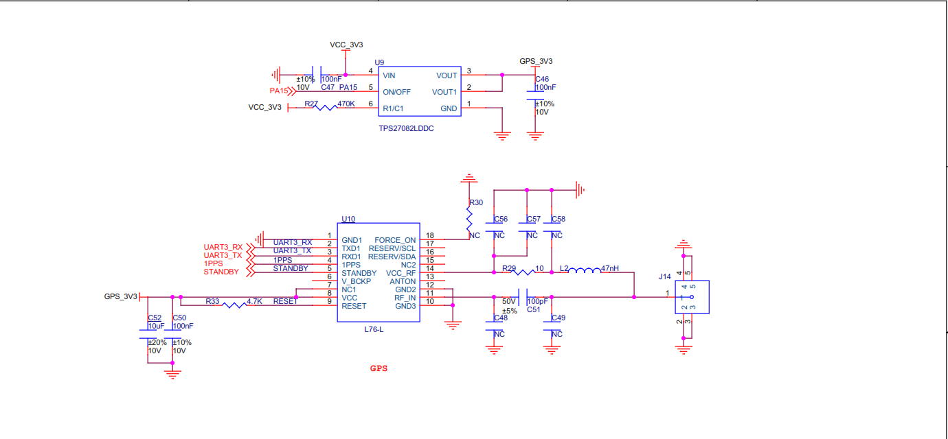
With no connection to the GPSs Vbkp pin, if you want to use hot fixing you can only use software shutdown of the GPS and that only reduces current to 500uA. Maybe the schematic is in error here.
There is a power switch to turn off the power to the GPS, which would reduce its sleep current to 0. However turn the power on and the GPS is starting from cold, with a typical run time of 40 plus seconds at 33mA, very battery unfriendly.
I can confirm that V_BCKP (pin 6) is not connected (measured with multimeter) to VCC_3V3 (nor GPS_3V3, nor VBATT nor VBIN) .
One would expect it to be connected to VCC_3V3 (which is battery powered). I also do not see a solder jumper that could enable it.
With some soldering craftmanship V_BCKP may be manually connected to VCC_3V3. According to the datasheet that would draw 15 uA (@3.0V) backup current for the MAX-7Q.
The power for the GPS can be switched off completely (with PA15), so if correctly switched off the GPS should not contribute to the measured 1.5mA in ‘low power’ / sleep.
15uA would be about right for a Ublox in software shutdown, but I was going on the GITHUB for the RAK 5206 which says they are using a L76. This matches the schematic.
If they swapped to a Ublox MAX 7Q, then they ought not to have left Vbckp floating, from the 7Q datasheet;
“If no backup supply voltage is available, connect the V_BCKP pin to VCC_IO (or to VCC if not avaiable)”
 If you are not seeing that come through check if you see it in the TTN console - look at you application data for the device - you should see all the different elements coming though…
 Settings then survive following board resets & cold boots…