Hello,
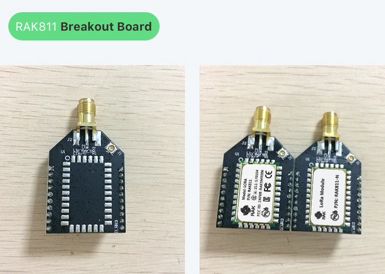
I am looking for the pinout of this RAK811 breakout from ALI :
Hello,
I am looking for the pinout of this RAK811 breakout from ALI :
It’s something like the XBEE pinout.
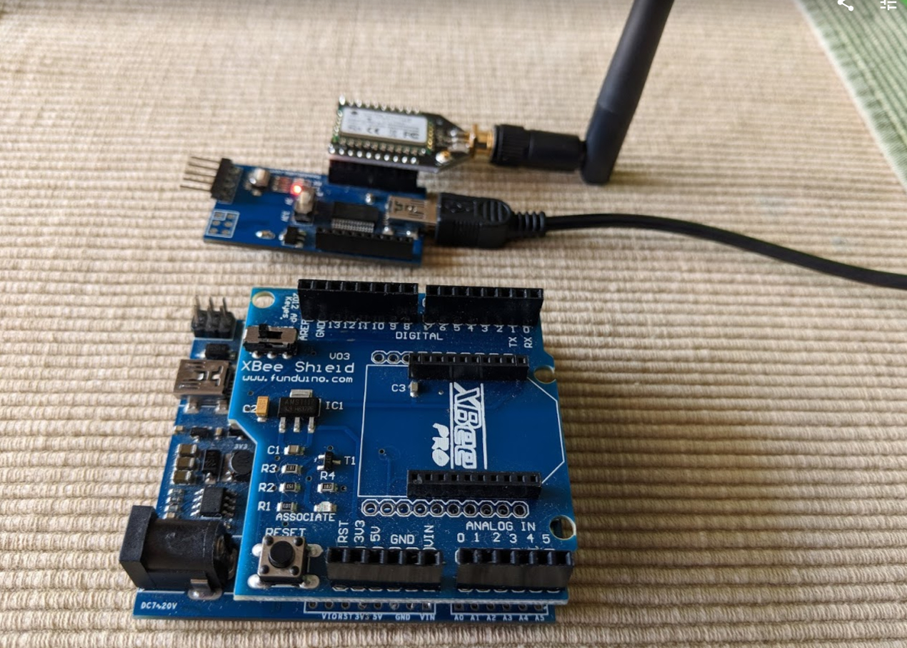
I connected it like this (XBEE adapter used to get it breadboard friendly):
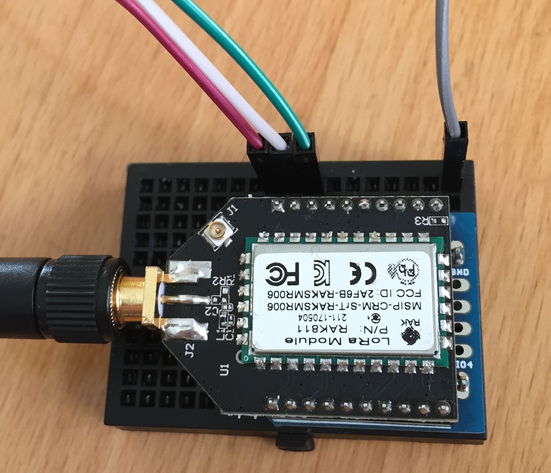
red 3.3V
white RX
green TX
gray GND
works like a charme 
thank you very much for your help
The pins are coming out the wrong side of the PCB. The schematic is correct (Pin 1 = Vcc) but the PCB is wrong (Pin 20 = Vcc). In my case I will remove the pins and insert them on the other side of the board.
This will work for the shield on the bottom but the adapter on the top of the photo doesn’t have space for the radio module.
I wrote an email to RAK, I hope this will be corrected in the future.
hey, I’m a bit new to this… Can I use atTiny85 with RAK811? I already have temperature measurement done with attiny85, I just wonder what else would I need to send it to RAK831 gateway with Raspberry pi?
And also, can I get farther away with just upgrading to bigger antenna on gateway? (I would need arround 600m without obstacles or maby here and there some boats)
why not… if you can program it to control the RAK811
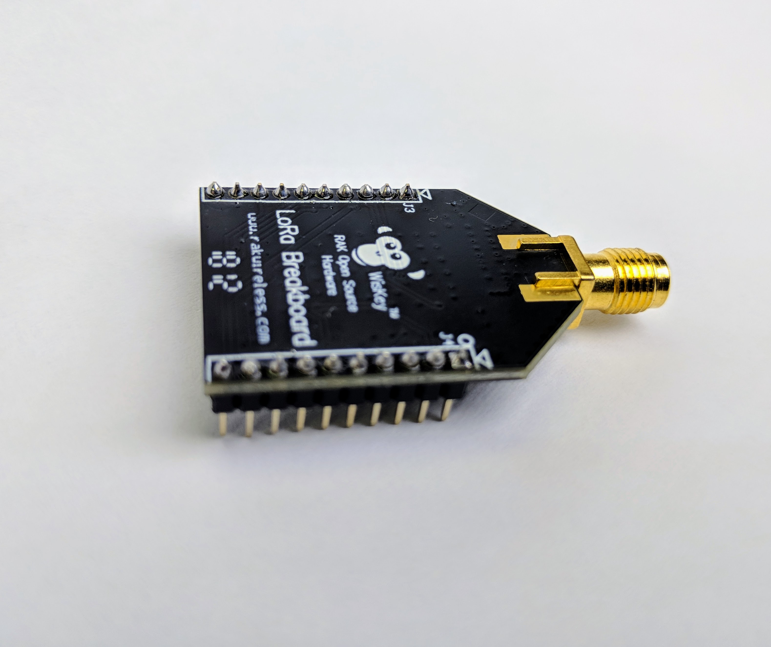
As a follow up to the pinout issue. It turned out that the board layout was fine…just the pins were soldered onto to wrong side of the board at the factory. Just like all XBees the radio is meant to be underneath. Just make sure the monkey is on top! The new RAK811s that I received all were soldered correctly.

Hey guysim trying to get rak811 working and send simple message to ttn but all i get is crc errors on my gateways
Any recommendations
that’s not enough information I’m afraid.
how did you connect that 811, did you use search, here or at RAK forum
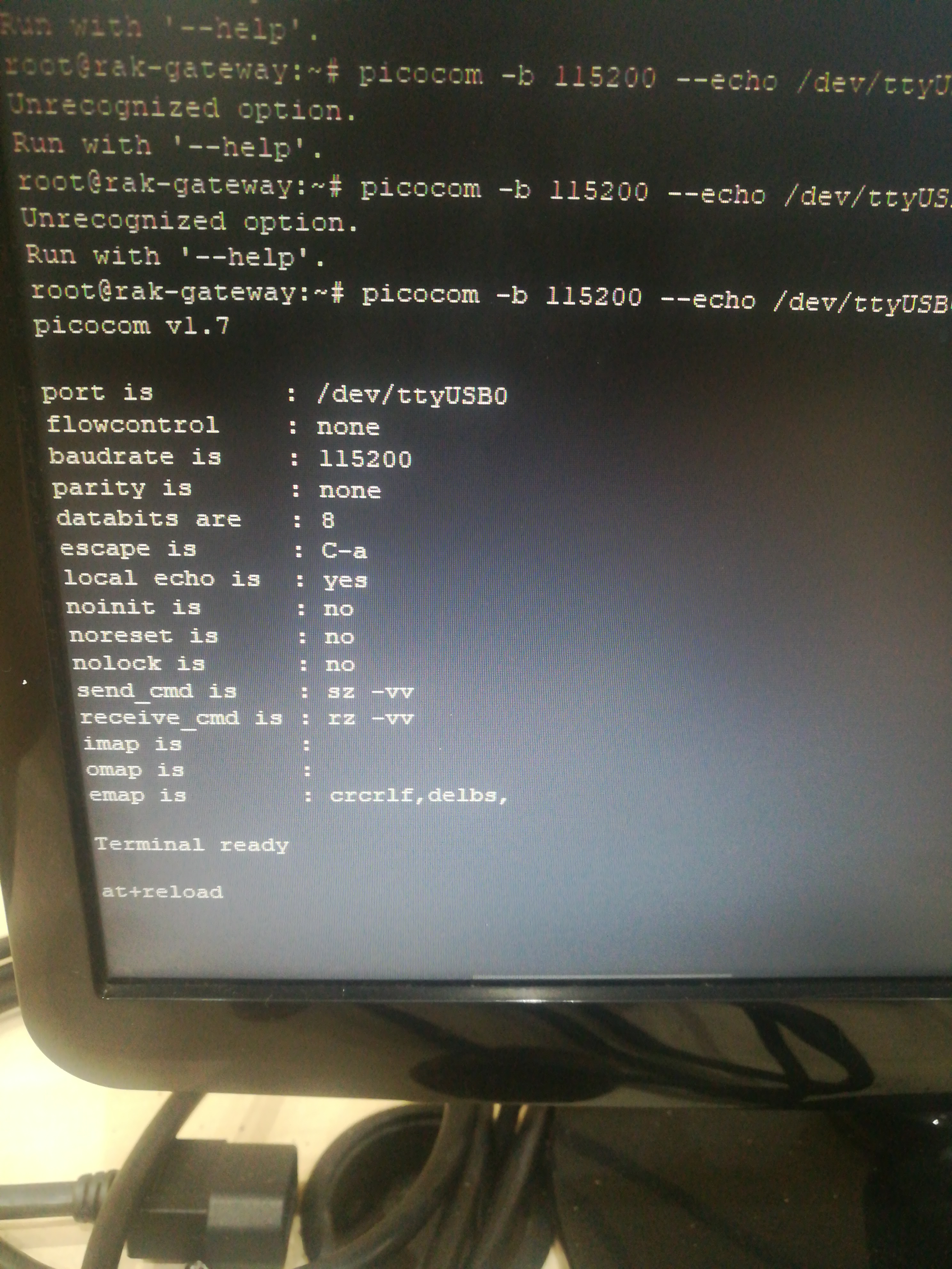
Hi @Wassimabbas, the following is a general dialogue that I use to get a RAK811 onto TTN using OTAA. This assumes that you are running the factory default firmware with the “at” command set. This assumes that you have access to the RAK “at” commands using a terminal. Something like:
pi@raspberrypi:~ $ sudo picocom -b 115200 --echo /dev/ttyUSB0
at+reload
OK
Note: this does a return to factory default.
at+mode=0
OK
Note: puts the RAK811 module into LoRaWAN mode, default is sometimes = 1 = P2P
at+get_config=public_net
OKon
Note: check that sync word is set to public = 0x34
at+get_config=dev_eui
OK35xxx…xxxx
Note: This is the Dev EUI, use this to register the device to an application on TTN.
at+set_config=app_eui:70xxx…xxxx
OK
at+set_config=app_key:C6xxx…xxxx
OK
Note: Use the info from the TTN console to set the app EUI and key for joining.
Note: Start looking at the TTN console for your gateway and application before trying the next step which is the join.
at+join=otaa
OK
at+recv=3,0,0
Note: This does the OTAA join with the response code of “3” being success.
Note: You should see the uplink and downlink of the join on your gateway and application.
at+send=0,2,000102030405060708090A
OK
at+recv=2,0,0
Note: You should see this hex data as an uplink in your application.
Hey thanks for your support.
The thing is that when i connect rak811 and opern serial i never get any messages even welcome to rak811 is not being received. I will try will what you sent and get back to you.
Regards
Hi @Wassimabbas,
If you use the picocom command in my earlier post with --echo then you should see what you are typing.
At the end of the command enter CTRL-m then CTRL-j to represent CR and LF. If you just press the return key then nothing will happen.
Still no response from the device
Hi @cultsdotelecomatgmai
Tried to do exactly what you suggested same problem no reply from device and not sending any welcome messages when i connect
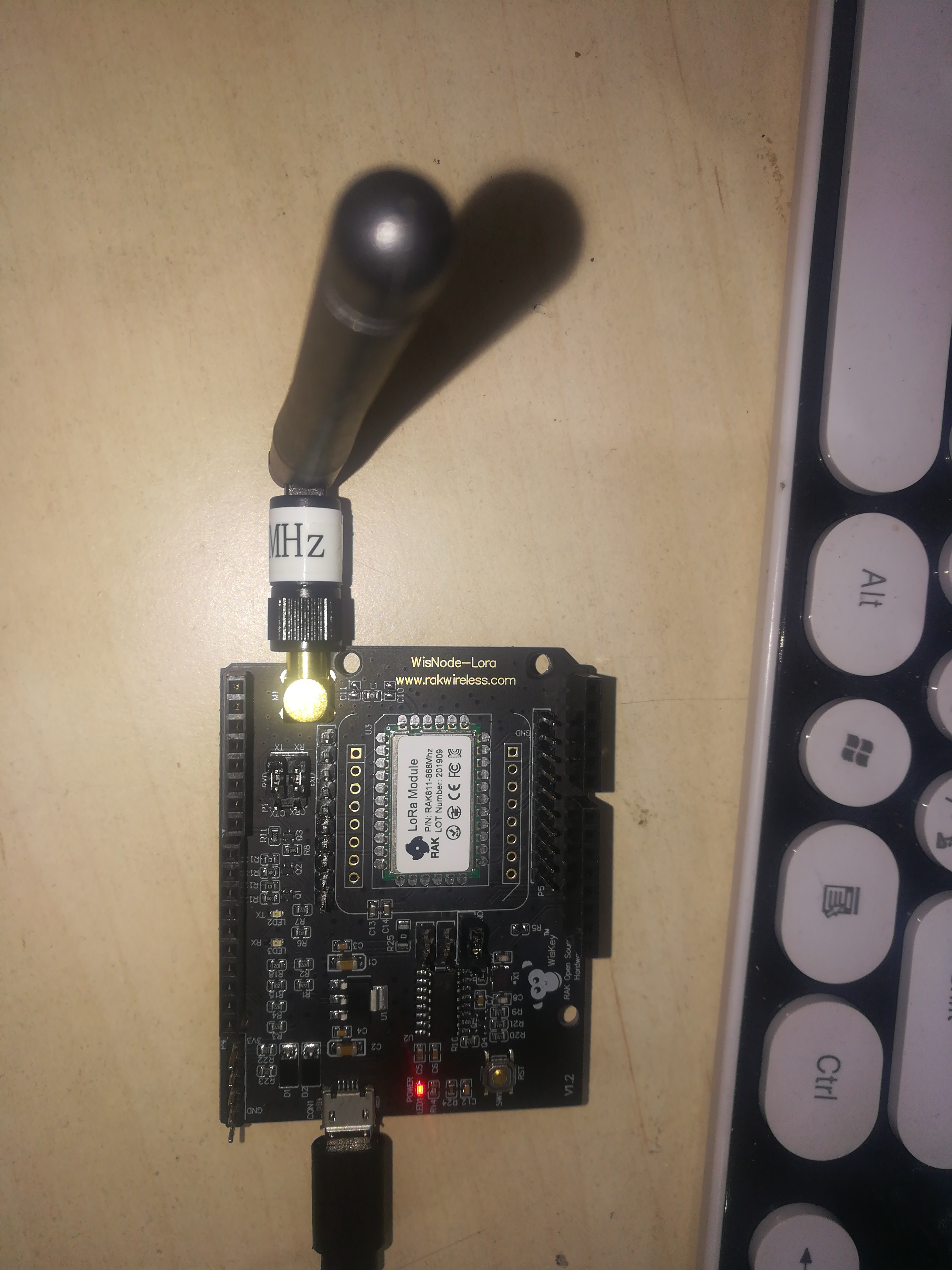
Hi @Wassimabbas, you appear to be using a RAK811 on a wisnode development board.
Please check that the wisnode is correctly jumpered to connect the RAK811 module UART to the USB serial. This is documented in the wisnode Quick Start Guide.
Please check that the wisnode is correctly jumpered for normal boot. Again, refer to the QSG.
Please try using the reset button on the wisnode. Again, refer to the QSG.
Please check the correct ttyUSB device no. on your system. The easiest way to do this is to remove the wisnode, run # ls /dev/ttyUSB* and then re-connect the wisnode and re-run # ls /dev/ttyUSB* to check which tty has appeared.
thanks a lot i used realterm and it worked.
Guys another question do you recommend using rak811 break board or wisnode to send temperature data to ttn as a testing node?
Hi @Wassimabbas, when I’m building prototypes I use a wisnode. For low-volume production I use breakboards. For higher volume I would use the module directly onto a PCB.