How do you check that (first window)? I have no idea how that would work on a LoPy4 but maybe with a little hint I can figure something out.
Also - would SF12 for RX2 maybe help out here? I know that it’s less friendly for the neighbourhood but if it solves the problem…
Or maybe decrease the 5 seconds delay? I do not fully understand its impact, but I am quite sure the gateway itself can handle a shorter period.
True! But I’d like to show the students which way it does work a bit unsatisfactory if it does not function as supposed
The device serial log doesn’t report opening a RX_2 window, so it must have received it in the first window.
No, I think far more understanding of what’s going on is required.
The most important issue is why two identical devices behave differently when side by side. Although the test you ran had different settings. Try having the devices at least 20m away from the gateway, same settings, smallish payload, uplink every 10 minutes, turn them on a few minutes apart, leave them to run for a few hours with your browser window open on both the devices (so that’s two windows) and the gateway. To save the console log, there is a very handy button to save it as JSON.
I’ll setup a webhook destination for you in the morning so it can also collect the data.
Decrease? It’s set to five seconds to give the time for the gateway to servers to gateway. The Rx1 5s delay after end of transmission is baked in as it’s part of the standard.
The other thing to look at is the details of any potential delays in the backhaul - so both the web console plus the logs on the actual gateway would show when the join request is heard and when the join accept is transmitted.
Thank you very much for the help and suggestions
Tomorrow I will be home until 3pm-ish but then neither be home or at school until Monday morning - so take your time! I will be at school that day for quite a couple of hours so I can leave them running with open tabs as suggested.
Because LoPy4 hides much of the stack that’s kind of hard. However a great way to check what is going on in an embedded device with LoRaWAN is to use a power consumption profiler. Transmissions and receive windows are clearly visible (if the other components do not use too much power),
The join delay? Not possible, the 5 seconds for the first join receive window are part of the LoRaWAN specification. Once joined (or while joining) the backend can provide the device with a different RX1 delay for normal downlinks. But join delays are fixed.
It does work the way it is supposed to. That might not match your expectations, but that’s something different. LoPy running python devices are not good to show/time internals of a LoRaWAN stack. Use anything running LMIC or loramac-node for that. (LMIC should be useable on the hardware but it might require some work)
Nodes not joining at some distance from the gateway or one node not joining when another does is all part of LoRaWAN. There will be differences (might be very small) that cause this, once you know them everything falls in place. Keep in mind some of them won’t ever become clear.
I just emailed the teacher support personnel and asked if there’s any such device in our posession. I’ve already been wanting higher time-accuracy than my multimeter so enough reason to check if we have something like that.
This will definitely be a student project one day… I’ve had my fair share of messing with the node software
I surely understand that… but I really need these boxes to have proper range since not that many students live within the 2.5km stable range… it would discriminate large portions of the classes that will be using these in projects. So in whatever ways possible I will try to push the usable range up to at least double the current distance.
And I know that we will first run the tests that @descartes is suggesting, but is ABP something that could be taken into consideration instead of OTAA? If RX sensivity on the nodes is the problem, it can be solved by using ABP. I understand that we would only be able to use our own gateway, and framecounters / device registration might need to be reset every now and then… but maybe?
(Note: this project has been started two years ago by someone who has been forced to retire due to chronic illness… so I have to work with whatever we have; I cannot just switch out to different hardware or platforms, I’m sorry)
Another thought - have you done any coverage predictions from the GW location - 2.5 - 3km doesnt sound much but can be very much influenced by topology of the ground and any building clutter/reflections etc. it may be your home is in an area with poor coverage? (You seem to be near the limits of reliable reception looking at the RSSI values). Look for areas with known good LOS coverage at similar distances and see if problem still shows if you relocate node there… Can you get up into high buildings at that distance? When you started posting I looked at your location and the e.g. A/c plant on your higher surfaces where you mentioned the GW is located but didnt investigate topology - will try and dig out again tomorrow to check local topology if I get a few minutes between dodging storms! - can you give an approx location for the remote node - understand if you dont want to disclose location detail due to privacy but an approximation (say 50, 100 or even 250m radius would be useful). Also have you eliminated the local aircon plant as a source of interference and potential signal blocking/absorbing/reflection - how high is the actual antenna (not the GW body) above the plant on the roof or is it inline?
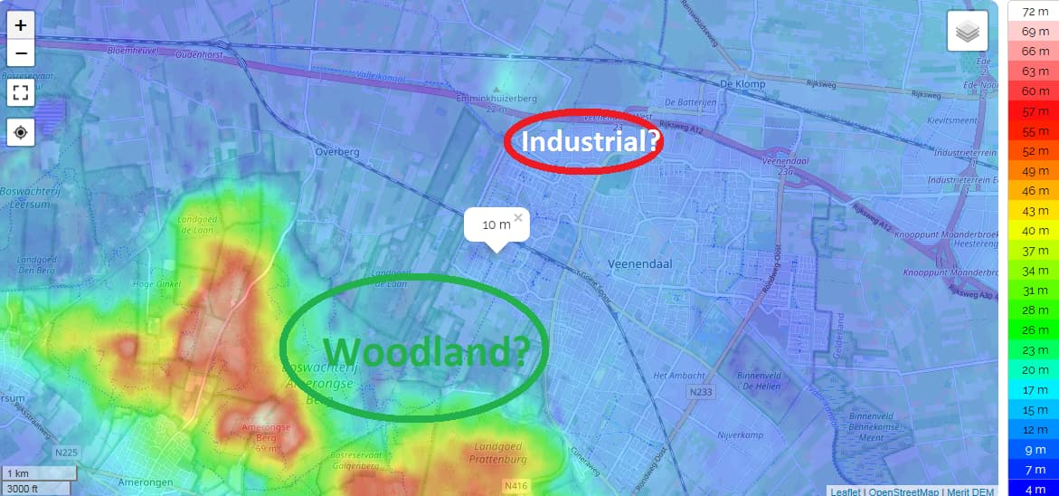
Update: A quick look around you shows you at around 10m local ground level. How high is Ant AGL?:
Depending on ant height and building heights getting much N.N.East beyond the Industrial area and A12 at ground level likely a struggle, the wooded area roughly south and south west/west will also attenuate depending on weather and of course getting beyond the higher ground further out south and west unlikely depending on topographic shadowing and ant height, the higher ground over looking your college should be good - but that looks >>your 2.5-3km. If at street level to east side (conurbation/built envornment and town centre area will get harder the further you get from the college and depending on height and materials you may struggle to get good signals into the town centre area. Does this sound right as description of your surroundings?
Well… that’s less of a quick look and more of a private investigation
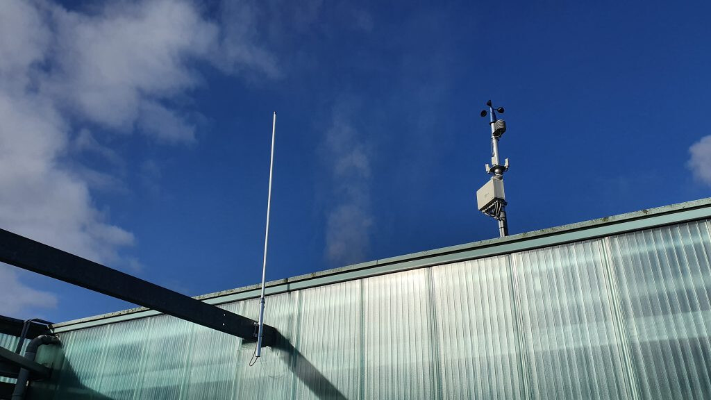
The antenna (in the foreground), on about 12 to 14 meter AGL:
I don’t know the exact model or so, maybe I can dig that out if wanted.
The antenna heatmap when it was on V2 was somewhat like this:
I cannot tell if this is the same on V3; all I can tell so far is that the antenna does pickup a WAY higher amount of communication compared to the popular simple black antennas as we use on the boxes.
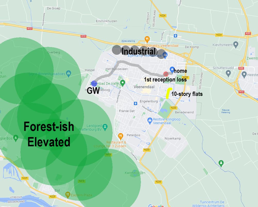
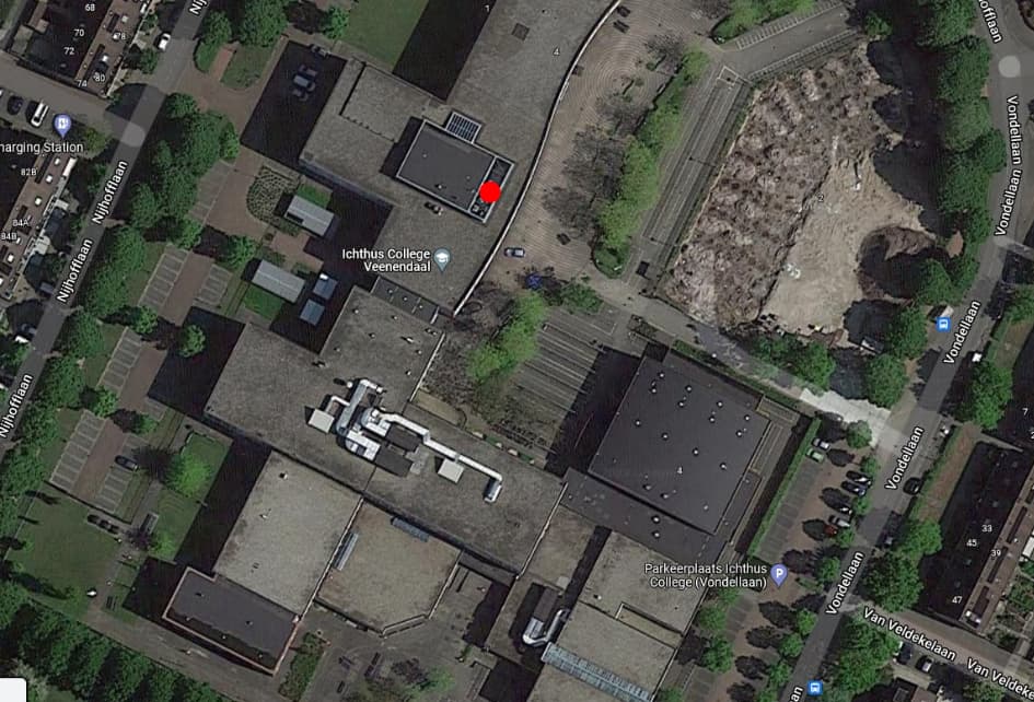
Your town analysis is mostly correct indeed! Here’s my map with some indicators:
The grey line is the line I took from school to home; the red dot the first time that the rejoining box did not manage to connect. I also indicated in yellow a spot with a couple of flats of which one or two are up to like 10 stories IIRC.
To be honest, I have never been out on the roof (photo is taken by the retired person), but I think the AC unit is oriented north with the antenna being on the south. The heatmap of V2, while my drawing may not be 100% accurate, does indicate that that unit should definitely not be a problem!
EDIT: It may also very well be possible that the antenna is facing east and the AC unit facing west; explaining why the heatmap shows bad reception on the west side. Will try to confirm antenna placement.
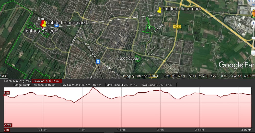
I have done a rough estimate of the two locations (College and Home)
Your elevation is fairly flat, varying between 8m and 11 m
If the HAVAC (AC) unit (will be a lot of steel plate) is between the two locations it will block the signal and you will not get a very long range. You will need to lift the antenna above this to get more coverage.
Confirmed that the antenna is ‘facing east’ with the AC unit on the west. I know that physics are weird with large/grounded metal plates but coverage towards my home should be mostly fine in that regard.
There is a reason why the emergency services use simple small antenna - they are closer to isotropic radiators. A simple 2-3.1dbi ant will give a far more even radiation (and listening) pattern. Higher gain antennae - which is what I assume is shown in the photo - may sound good on paper and may even help reception coverage at a distance (hence the potential 15km range). BUT they introduce other complications. With EU legal limits you need to reduce your GW TX power to compensate for the excess gain of the Ant (its a zero sum game!) - if who ever set this up did that correctly you may hear a node in poor coverage area but the node may not then hear the GW respond (e.g. with join accept.). Some of your data shows received node RSSI at the GW at around -118 to 120, implying that if gain is >around 6 or even 8dbi and adjustments made correctly the node may see a signal several db lower - even with an ideal ant and may not hear properly! Also the gain is concentrating the enegy into a naroow horizontal beam to reach further to the horizon, and in doing so it reduced the enegy radiated closer in and in higher gain antennas may even introduce notching - with are areas of deminished energy at varing distances from the ant. These then respresent rings of poorer relative coverage centered on the gw - a bit like ripples in a pond. Also higher gain ants may introduce a degree of beam tilt depending on what application they are engineered and optimised for. An ant designed for use near ground but intended to communicate say with airborn receivers will have an up tilt, an ant for use on a tall mast or hill - say for broadcast radio or TV type apps may be inclined for beam tilt down to get to ground cover and maybe into valleys etc. Personally I would initially look to check coverage over wider set of points to see if this is indeed an issue and better yet would simply look to replace with a known good basic outdoor rated 3dbi ant on basis of offering highest probability of most even coverage all around you site…
Whilst the antenna location is clearly something to sort out, I still think we need to check that both devices perform the same when they both have the same firmware on them, otherwise much effort will be expended fixing other things when one of the devices is sub-optimal.
There is the lora.stats() function that returns a nice tuple of tech info, if that got printed to the serial log after each transmission, perhaps using the lora.callback() on all three events.
I use CoolTerm as it puts timestamps on for me, will capture logs to disk and is available for macOS, Win & Linux. The main thing is having timestamps.
Once they are running for an hour or so, make them rejoin, just not at the same time.
Nick is correct wrt sorting nodes (same hardware/firmware/operating config really a must do for true comparison and debug).
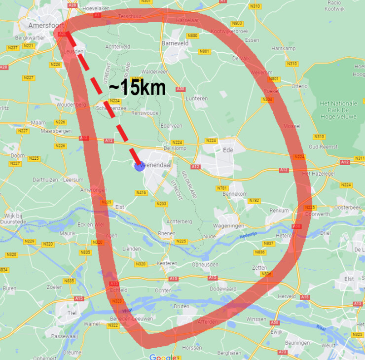
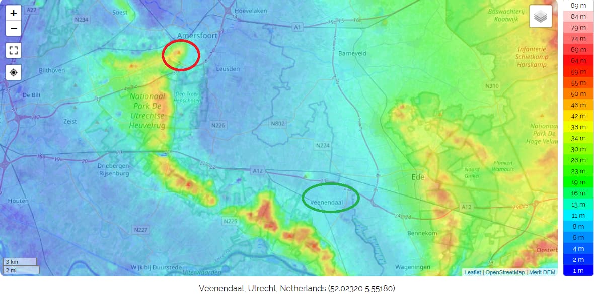
Meantime looking further at your 15km trace I would note that Amersfoort is much higher (in relative terms) than GW location potentially setting a false expectation with respect to coverage and range…
I saw a similar situation with one of my communities a few years back where high spots in a generally flat area were providing hits 10-15km out but closer in where we were hoping for coverage (in this case from Wendover at the foot of the Chiltern Hills to around Stoke Mandeville village and Stoke Mandeville Hospital 3-5km away) coverage was very spotty and intermittent. https://www.thethingsnetwork.org/community/aylesbury/post/1st-coverage-test-results
Yes Nick, I will definitely do that. Next week (if equipment arrives in time) we will be calibrating both devices against a whole series of CMA equipment, for maybe even like two full days.
On Monday, I can run a ‘simple’ test without calibration, just logging. The lora.stats() function may not be as useful when only transmitting, but I will try to set up CoolTerm or something related.
I do not have full access to gateway logs (SSH seems to get stuck on the school network), but hopefully the webhook you mentioned or the general logs will suffice.
Regarding Jeff’s comments: that may very well be happening… hmm… Amersfoort and the Veluwe (elevated on the right) could be ‘false positives’.
Is there a not so time-consuming way to map basic coverage? Besides rolling out all 60 devices and just handing them out?
Give me 24hrs and I will try to come up with something - can you confirm the Ant height as that massively impacts the predictive models - obviously being close to the roof-top plant will drastically impact real vs predicted unless you can get the ant above this as suggested by Johan above.
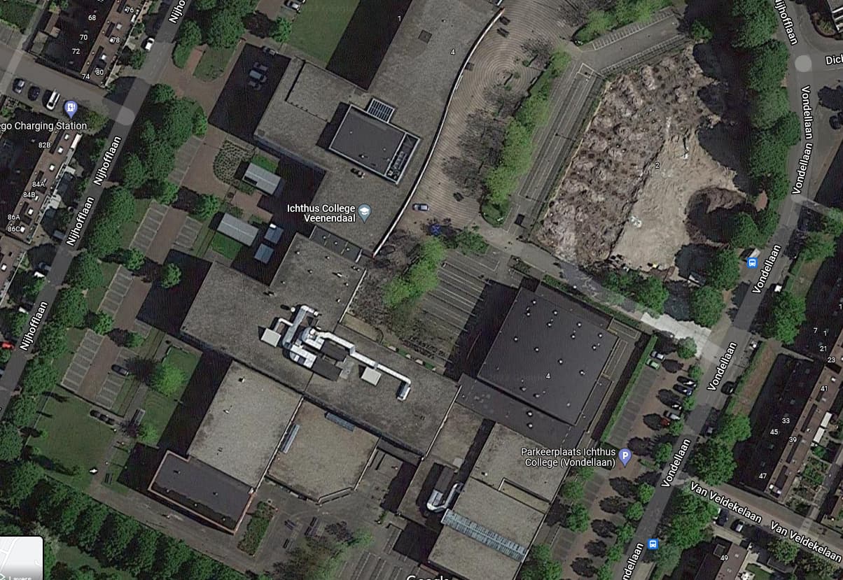
Can you show placement of ant relative to plant on the picture please:
Best I can do is an educated guess on antenna elevation right now.
School itself is three stories - classrooms are usually 2.5 meters high around here. So a small 3 meters per floor and a robust roof makes for 9 meters ground to rooftop itself. Then there’s the AC-unit which is about 3 meters tall. So the antenna is most likely between 11.5 to 12.5 meters above ground level.
That’s ok so approx 20-25m above MSL. Was worried the a/c plant you mentioned was the big set up south/south-west of your dot on other building section! That would be bigger issue.