Hi guys!
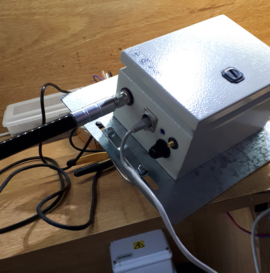
This week we´re installing this antenna in a 30mts tower:
With a IP-65 enclousure using RAK813 gateway:
Our goal is to cover several end devices (street lamp modules we´ve made) and this is our first field test!
The ideal coverage: 10km. The nodes are going to be 9mts above ground so I think that it will work
I will let you now how it goes! If you have any advice, it would be great!!
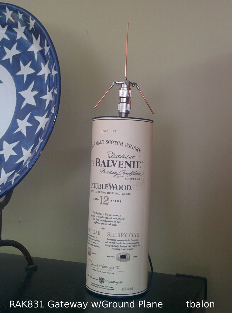
Finally found a use for one of my empty containers …
I added my newly constructed ground plane tuned for 915 Mhz to my gateway. Tremendous improvement in signal quality. Was easy to build but took a bit of tuning to get it just right. I used my NS1201 VNA.
Could be a topic for on te work bench thread.
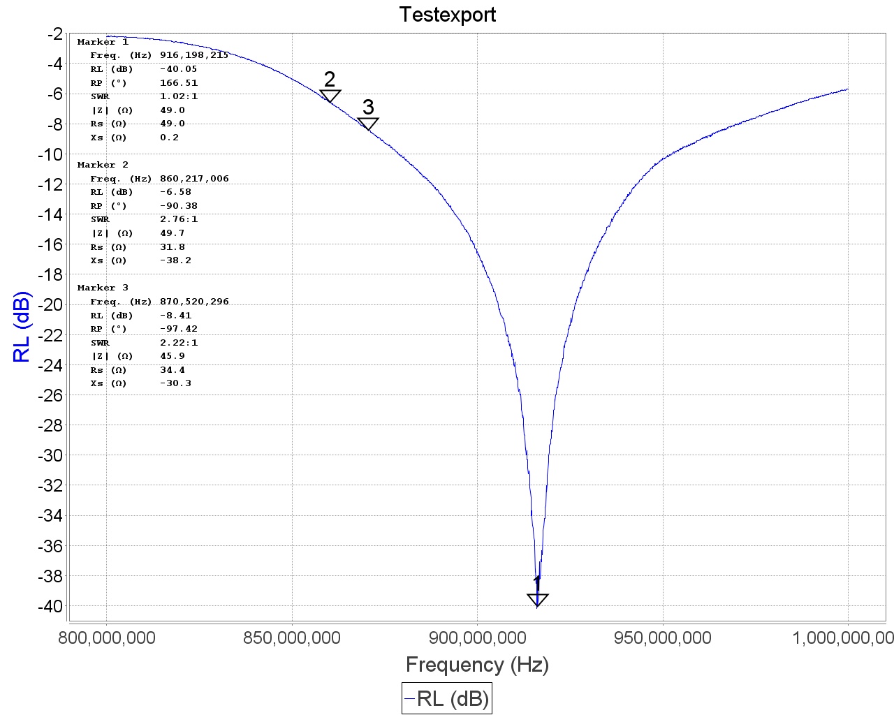
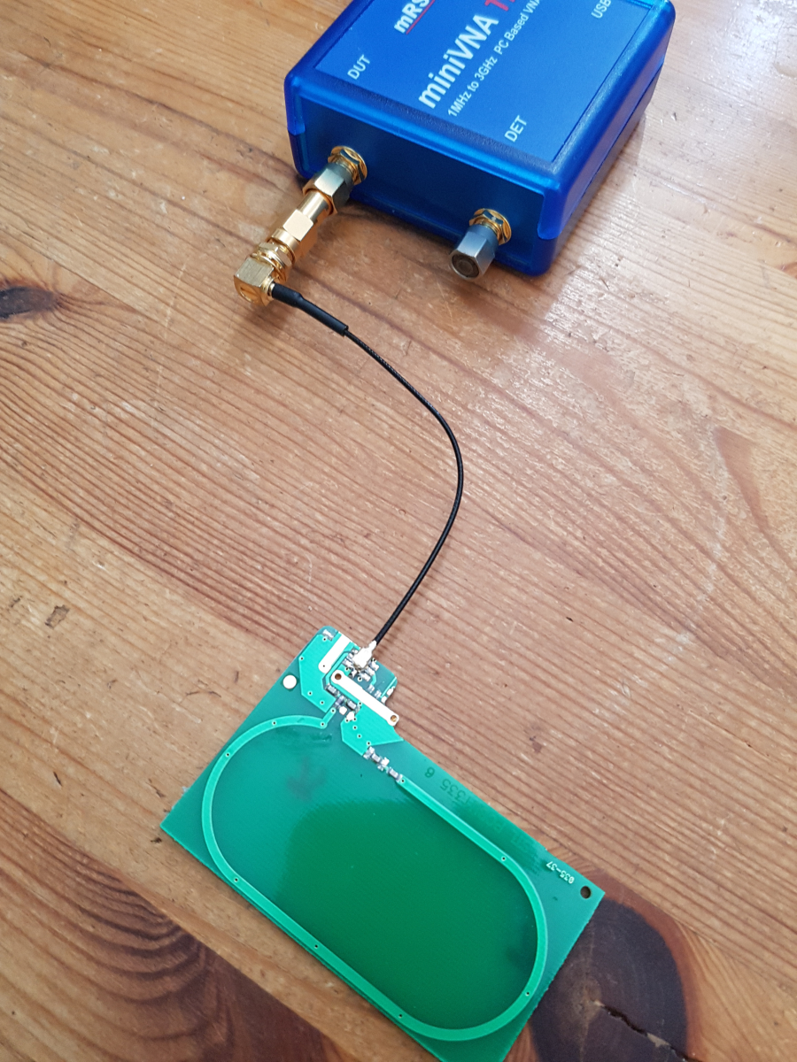
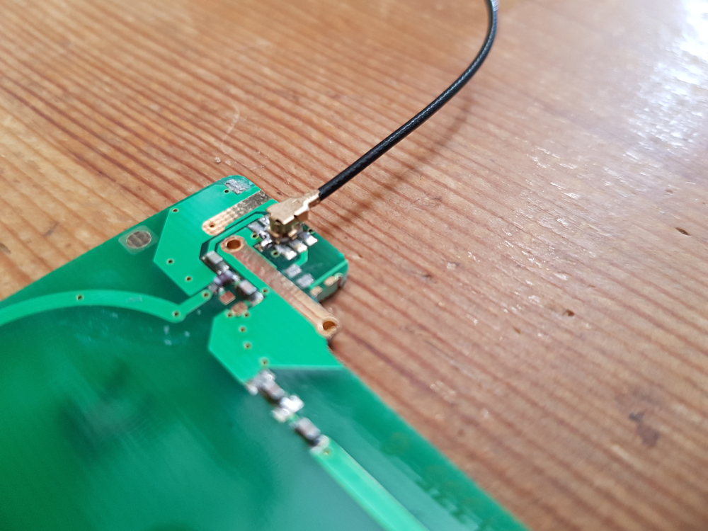
I have measured the antenna I found in a device for elderly care.
It was told to me to be om 868 MHz. bu the device seems tuned for the US market eg. 915 MHz.
The container is made of compressed cardboard… so no real impact from the container itself. That being said, the top is metallic. Some sort of tin or aluminum …
To get a good match I had to tune the antenna once mounted on the top of the canister. The additional ground formed by the metallic top changed its impedance. All that was required to compensate was to change the angle on the ground radials so that the impedance at 915 mhz was 50 ohms. There was a small hole in the back of the container and I ran the feed line out that and connected it to the VNA. You can see the radials are not quite 45 deg.
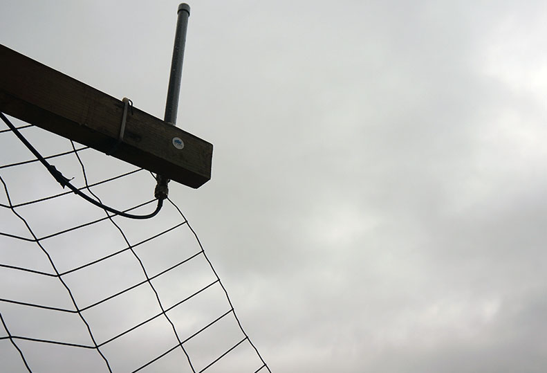
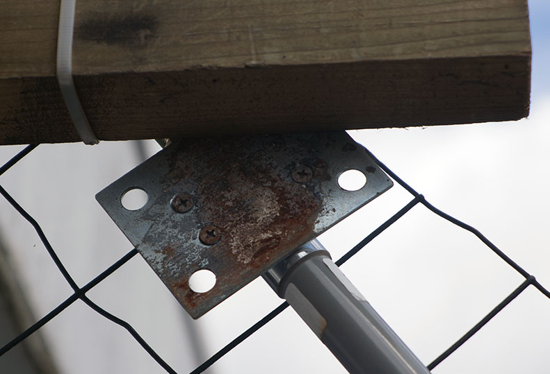
Yesterday I replaced my 10 Dbi for a 3 Dbi (testing)
Doing that I found… rust
observation 1 : because this antenne is 2/3 smaller it’s not sticking anylonger above the apartment rooftop… hence it seems that it’s very directional now, probably using the concrete iron as a reflector.
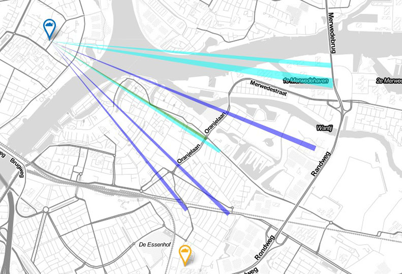
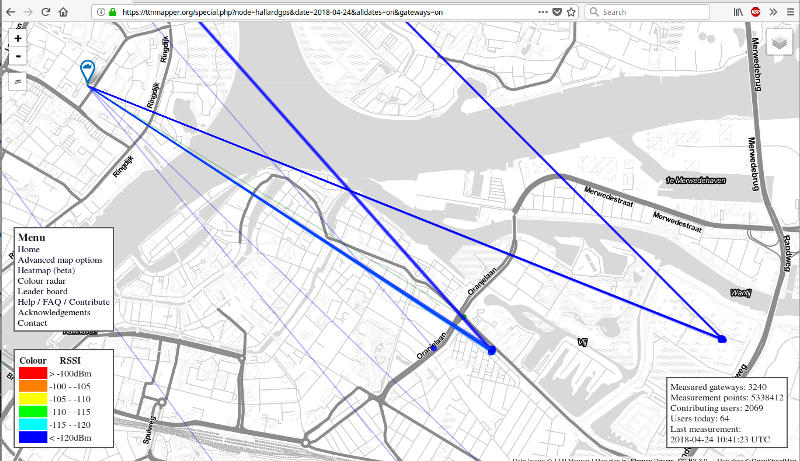
Yesterday evening I was in Dordrecht. My gps_ttn_mapper node was seen by 2 gateways, one in Rotterdam and the other was yours
For a few hours I was at the local radio amateur club PI4DEC and a little later I visited a friend at ‘Noordendijk’ both resulted in a cluster of dots.
Used node is a hallard-pcb with pro-mini, rfm95 and a Neo6 GPS, SF7 and a 85mm wire antenna, placed on dashboard of my car.
b.t.w., I believe we have met a very long time ago at the studio of Wick and also in your KCS-office.
Too late to update my post 433 (on how to change a 915 Mhz antenna to 868 Mhz)
So posting here.
I thought I’d check the stock antenna provided with the TTN gateway - sure enough it was set for 915 Mhz.
Not only that it looks almost identical to the cheap Chinese one I bought from eby.
So I swapped with one of my doctored antenna (as seen in previous post) and sure enough the RSSI improved for the gateway !
Be careful though, the antenna is fragile and easily broken - I would buy another antenna and doctor that (and keep the supplied TTN antenna spare). Going to buy a few more of these cheap antenna of Eby now !
Hi CurlyWurly,
I did what you did (10 posts up from here) with a cheap antenna. Mine was even worse than yours, it originally had a VSWR of 12 and an impedance of 150+j250 ohms on 868MHz. It was tuned for 975 to about 1200 MHz and would have probably performed well on the 1090MHz ADS-B airplane band
Not only enlarged the center conductor but I also enlarged the brass tube at the bottom by soldering a flap of thin copper foil around the tube, making it about 15mm longer. Because of the copper foil it was not easy to slide the plastic top back completely therefor I slided it back partially and did a piece of heat shrink tube around the base. So the result was about a 1cm longer antenna
After the modification it behaved very well on 868MHz. Putting it on my RAK831 gateway it got at least 5dB better RSSI signals compared to the short stock antenna that was delivered with the RAK.
With my antenna, the intial VWSR was 2.72 - You’ve done well in getting it work from 12 !!
Any chance of uploading a pic and showing what you did - also showing the VWSR result?
I’ve just ordered some more cheap antenna to try.
Unfortunately I couldn’t get the same ones again - It might be that I have to do what you are doing?
@ CurlyWurly
Soon I expect another cheap 868 antenna which will very likely not work on 868 because it is for 915 or higher frequency. When I remake that antenna to 868MHz I will not forget to make some detail pictures and give some dimensions so others can do the trick too. The one I modified is sealed now,
I own several of those pictured books. The ARRL Antenna Handbook is a good book, it covers many antennas from about 100kHz upto about a GHz. Not dry theory but lots of diagrams pictures and practical designs. But mostly for shortwave, not much for VHF/UHF.
There exists not yet a LoRa Antenna Handbook, that would probably be a big hit
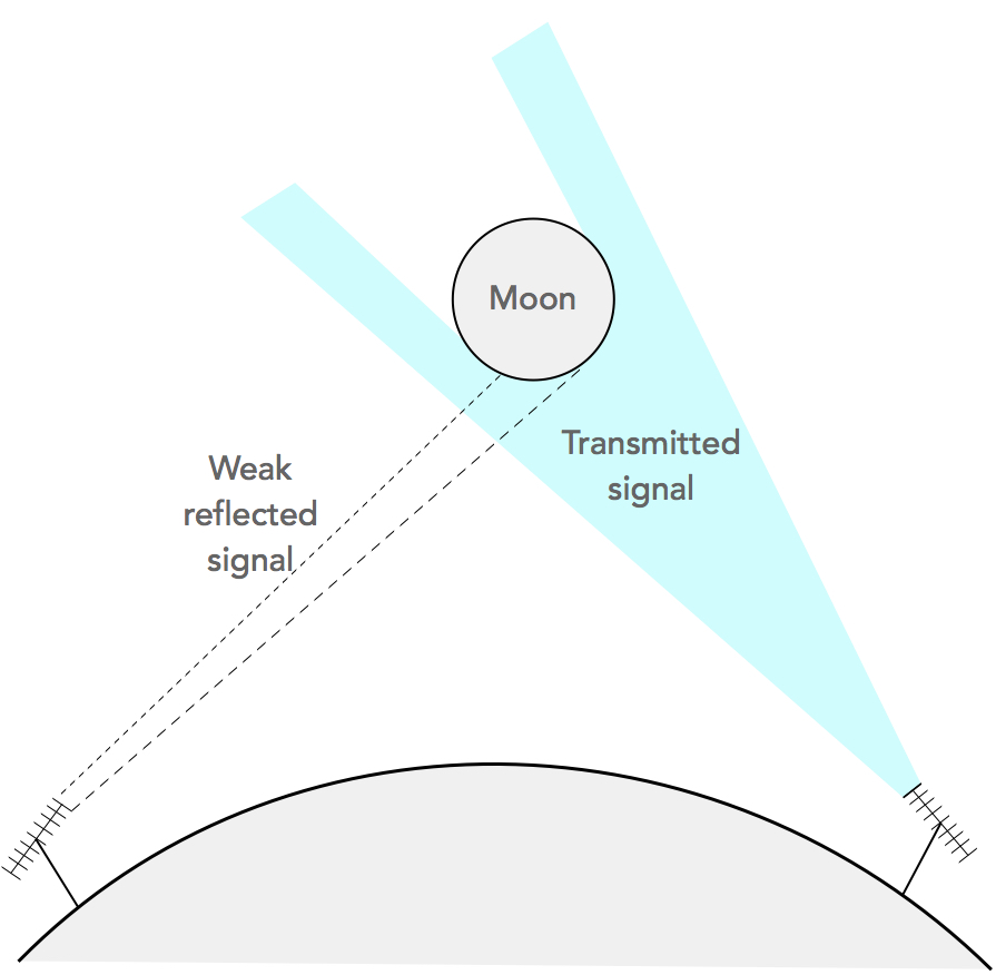
Moonbouncing or EME (Earth-Moon-Earth) is about the highest level of communication sophistication for ham radio amateurs. Can it be done with LoRa? We certainly need BIG antennas.
Here’s an unconstrained exercise to understand what it takes to send LoRa signals to the moon, and back.
The best possible Lora receiver sensitivity is -136 dBm at SF12 and 125 kHz.
Assuming 1000 watt (!!) transmitter power, and using surplus 10 feet diameter c-band satellite antenna dishes for transmit and receive, the link budget could be as follows:
TX 1 kW: 60 dBm
TX Antenna gain 27 dB (10 foot dish)
TX antenna cable loss: -3 dB
Estimated path loss earth-moon-earth at 915 MHz: -260 dB
RX Antenna gain 27 dB (10 foot dish)
RX low noise amplifier: + 24 dB
RX antenna cable loss: -3 dB
Its used to measure the gradual drift of the moon away from the earth…eventually there will be no full eclipses as disk with appear too small in front of the sun! Believe it’s some sort of ‘quadrant’ reflector (not sure correct name) - think one corner of inside of a cube with precisely aligned mirrored surfaces that effectively reflect incident light back along the ‘same’ path to sender…pity it doesn’t work for LoRa e.m. wavelengths!


 Believe it’s some sort of ‘quadrant’ reflector (not sure correct name) - think one corner of inside of a cube with precisely aligned mirrored surfaces that effectively reflect incident light back along the ‘same’ path to sender…pity it doesn’t work for LoRa e.m. wavelengths!