I only have three, so better know in advance (but will discover it for real only when soldering, and can’t change them anyway). They come from AliExpress so you never know for sure…
I have had some Chinese scope leads with pretty bad BNC connectors where the insulator material was PVC like (and the pins easily broke).
You did make a nice 3D soldering stand. I will have to do without it. Will probably be quite a challenge to solder the correct angles.
You can use the CAD design (OnShape link is at the bottom of the blog page) for dimensions. I am not sure if you can measure stuff without an account though but try to select two points, the distance is then shown in the bottom right corner, if not you can just create an account, it’s free for hobby use.
The connecter I used is also very cheap from Aliexpress and it still was PTFE, the center part bacame loose when I tried to press on the antenna so make sure it fits before starting to solder.
About the ground reflector length: I think I did take the extra length into account, the actual length came from the simulation I did which may have been inaccurate but the measurements confirm that the design works as is. I made two antennas like this, one I measured, the second one I just built using the jig and it performed just as good if not better. If you bend the ground reflectors wrong it will still work, the far field will just not be a perfect donut but a slightly distorted one. Bending the reflectors can even be used to get some additional gain in one direction.
But you can ruin any antenna with bad placement. A friend found this to be a bad antenne - when mounted next to a steel drain pipe
And if your neighbors start complaining about a 2m long pole on top of your roof or if the roof is accessible for more people, then a small antenna like the small DIY GP from schneider_da might be better,
At the end it all depends on the amount of money you want to spend on an antenna and where you can place the antenna. In my friends case, we could not get on the roof and there is no allowance to drill holes in the wall so we had to choose for a small antenna in a piece of PVC pipe that could be tywrapped to the drain pipe (with the antenna above the roof of course).
That antenna is a home built J-pole (https://m0ukd.com/calculators/slim-jim-and-j-pole-calculator/). The best antenna in this case: light, slim, less visible to visitors and accepted by the land lord
The analyzer will probably function as a ground plane for the antenna.
When you pick it up/move it, could it be that you influence (extend) the ground plane with your hand/body and that this effects the measurements?
Some thoughts:
I am no expert but I would not be surprised when the analyzer itself would influence the antenna measurements, because of the ground plane effect which may skew the results.
If so then adding a cable between antenna and analyzer will probably reduce the effect (but possibly introduce other side effects).
In other words, how reliable is the measurement when the antenna is directly mounted on the analyzer?
How representative is the analyzer as ground plane for real world situations, and would it maybe be better to add a cable (short enough to be of minimal impact but long enough to reduce analyzer ground plane effects) between analyzer and antenna to test the antenna in a (from ground plane perspective) more representative situation?
Have the same issue, as soon as I move the device, all is changing, best measure (I think) is leaving the device like on the picture (on a table or desktop) without touching it, looks like the best option.
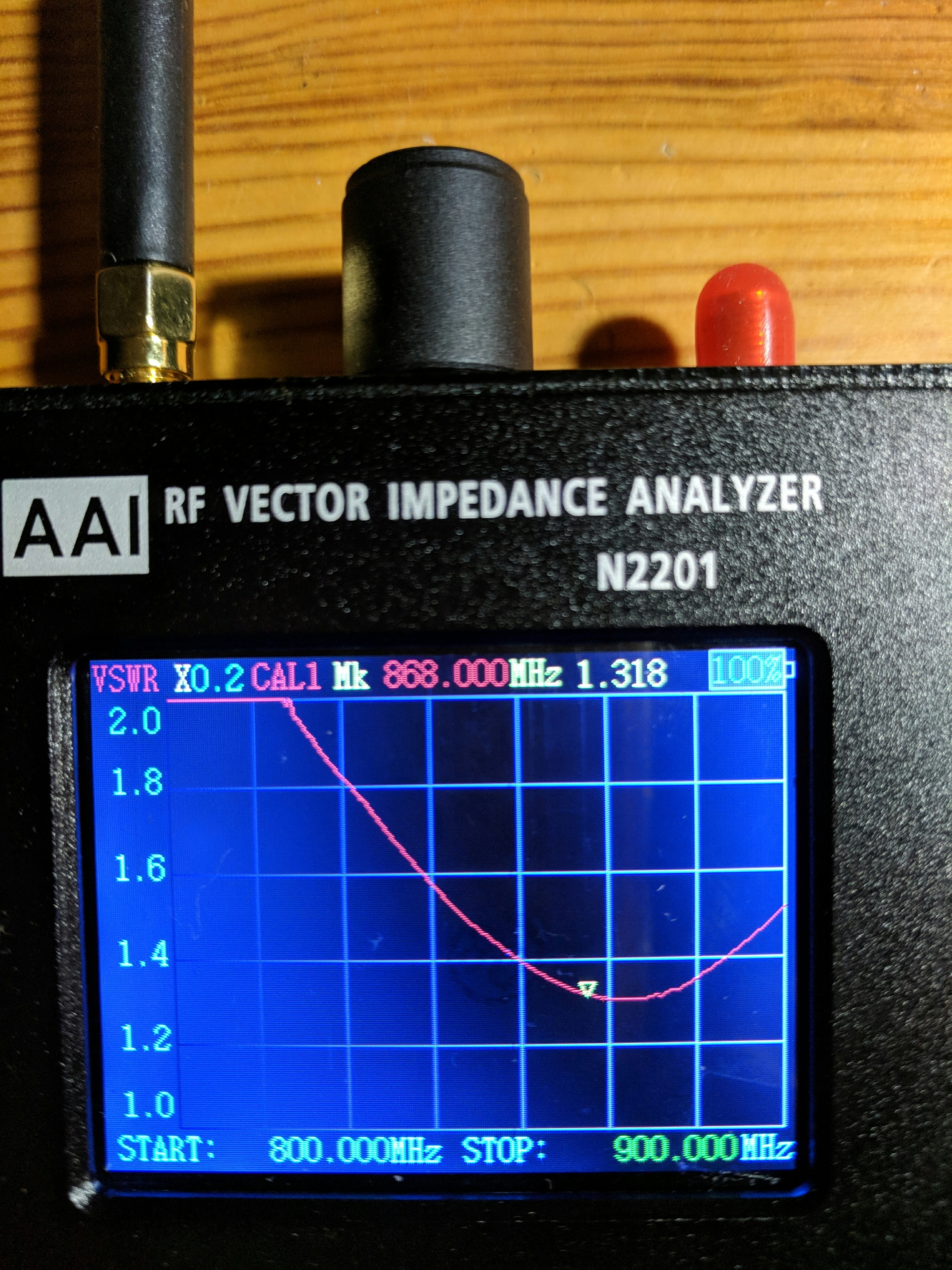
Got my N2201 from Ali today (163€ total, arrived after 13 days). Did also test the Heltec antenna, see picture. Looks like this antenna ich much better than expected. VSWR 1:1,2 - 1:1,3 is an excellent result, i think (?)
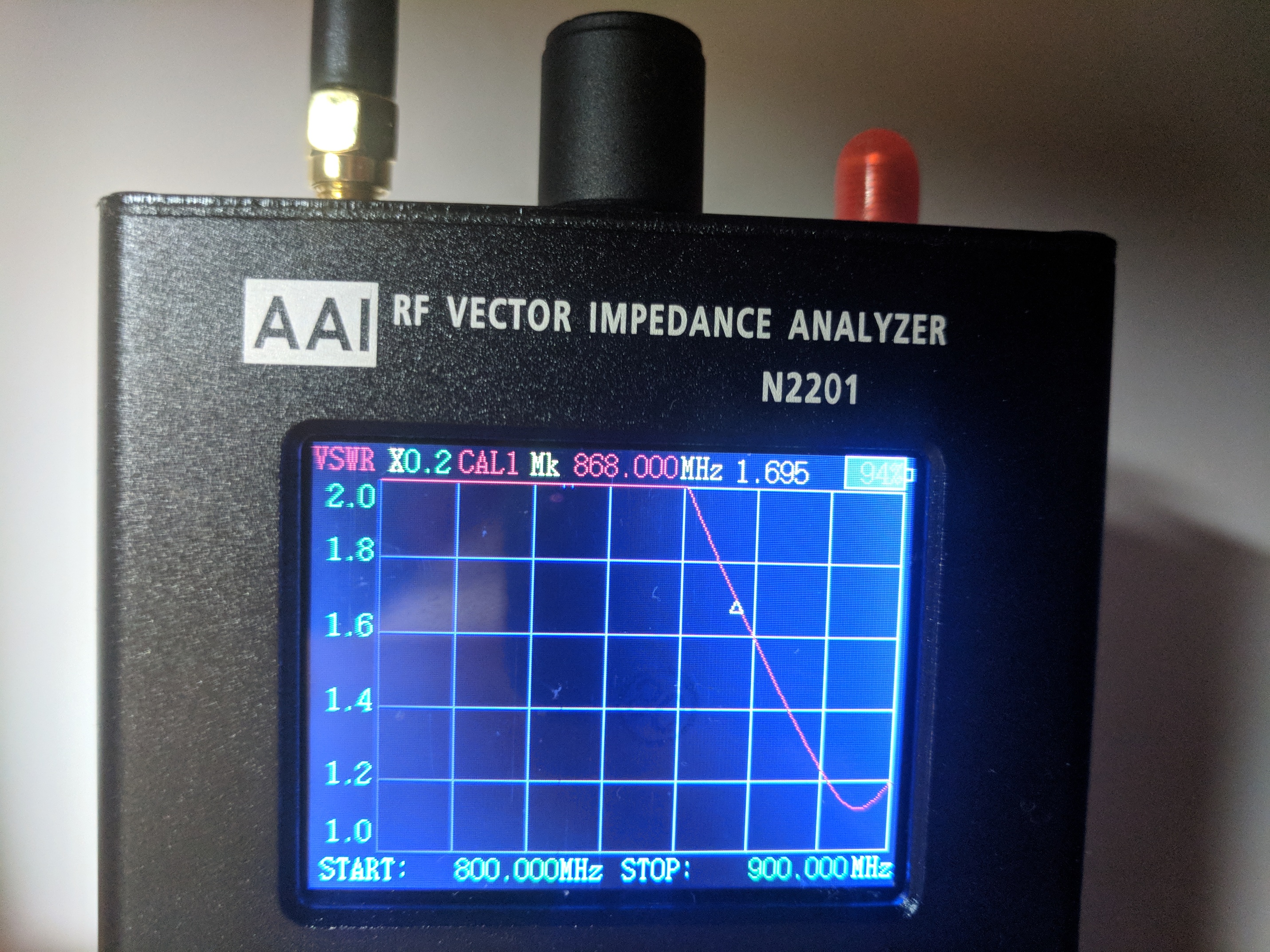
FYI: A larger ground plane will lower the center frequency and widen the bandwidth. That effect is clearly visible on your pictures and shows that a ground plane has a substantial effect on the antenna’s functioning and performance.
I don’t have an analyzer like the N2201. But it would be interesting to see some tests with a cable between the analyzer and antenna and test with different ground planes. (See some posts higher up.)
If I remember correctly, a good ground plane for a quarter wave mono-pole should be at least half a wave length in diameter and be ‘grounded’ (connected to mass of the antenna).
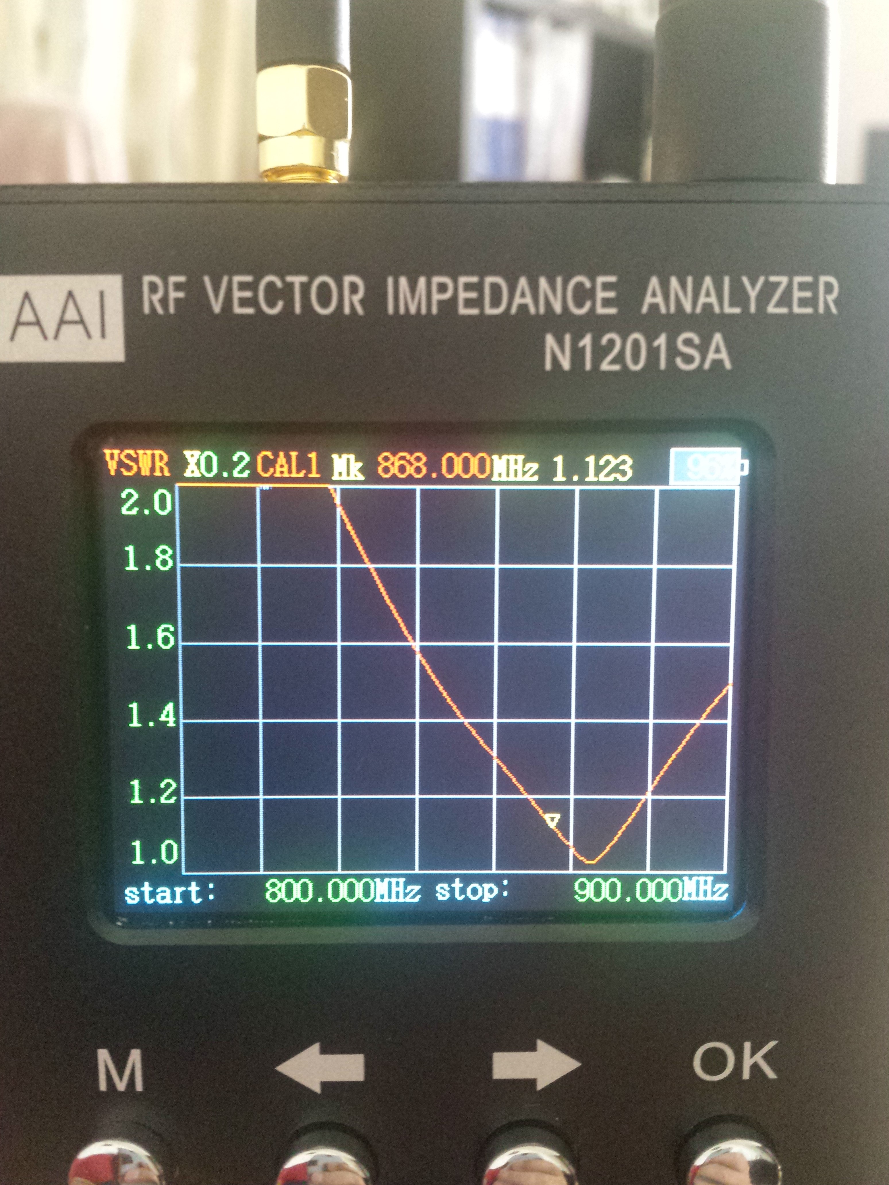
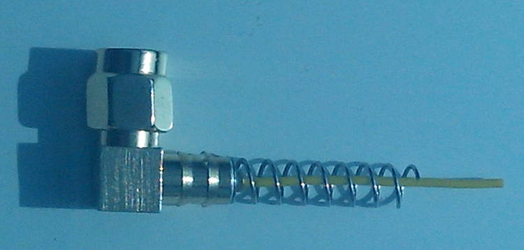
I did some measurements with a N1201SA antenna analyser on two small antenna´s about 50mm long. I got those antenna´s with my Pluto SDR receiver from Digikey. Those are specified as general purpose UHF antenna´s. Inside, connected to the center pin is a straight wire of about 30mm surrounded by a coiled wire 20mm long soldered to the outside of the connector.
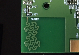
antenna without plastic cover.
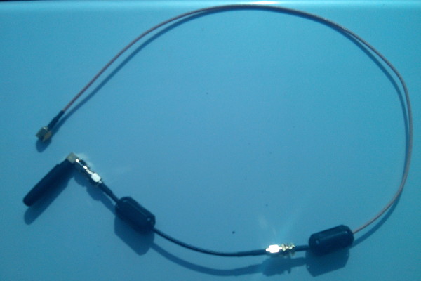
I measured the antenna directly on the N1201SA and also with several lengths of 50 ohm coax with a clamp_on ferrite choke close to the antenna side of the cable.
Directly on the analyser the antenna resonates at 820 to 825MHz with a VSWR of 1.1 to 1.2. Dependent on the place of the analyser.
Then I inserted some cablelengths, 15cm, 50cm, 65cm and 100cm with ferrite choke. Holding the antenna by the ferrite clamp so there is no handeffect. With all cable lengths the antenna´s had a resonance frequency between 865 and 870 MHz and a VSWR between 1.05 and 1.35.
Best result I had with a 50cm plus a 15cm cable which including the connectors was 68,5cm. Because cable_velocity factor = 0.66 the electrical length for the cable is 103cm which happens to be 3 wavelengths at 868MHz. When cable_length is a exact number of electrical (1/2) waves, the analyser just sees the antenna and ignores the cable. With this length of cable the antenna resonates at 867MHz with a VSWR of 1.05.
So it seems to be a good 868MHz antenna.
antenna with 65cm of cable.
Conclusion for this type of antenna´s is that the working is strongly dependant on the device it is mounted on. Meaning the amount of metal that functions as a groundplane. The antenna analyser is, compared to the antenna, a large chunk of metal. I think that is the reason that the resonance frequency was lowered by 45MHz when directly connected to the N1201SA.
Also I wonder how effective this short 30mm wire surrounded by a grounded coil can radiate. I believe that a single straight wire of 85-86 mm long directly soldered to a device is a more effective radiator than this short antenna. But sometimes you need a small antenna for a small device.
Note: without the plastic cover the antenna resonates above 900MHz