I bought 10 of these to test with a LoRa32U4 (bsfrance) to a TTN gateway.
Whilst not really a scientific test, I just swapped the antenna to check if there was similar performance seen at the gateway.
Even though they look identical, I was suprised to see how much they vary (from -51db to -91db). However most were at the better end.
That is quite a lot. Antenna’s from a single batch should be expected to perform similarly. But it is hard to see if they come from the same batch (same manufacturer even). Large differences in a single batch can indicate quality issues.
An example is the above antenna included with Heltec and TTGO boards. Even while the antenna’s appear identical one of them appears about 2mm longer than the other which can have quite some impact. (In a simple test I measured 8 to 10 dB RSSI difference between these two antennas).
Being a techy geek, (jack of all trades and master of none - especially RF), I would appreciate comments on the following: I wanted to compare how effective different antennae would be and so setup the following test rig - see photo below, showing SDR, RF-bridge with 50ohm reference and noise source, running rtl_power (RTL-SDR) and scanning from 50MHz to 1.5GHz.
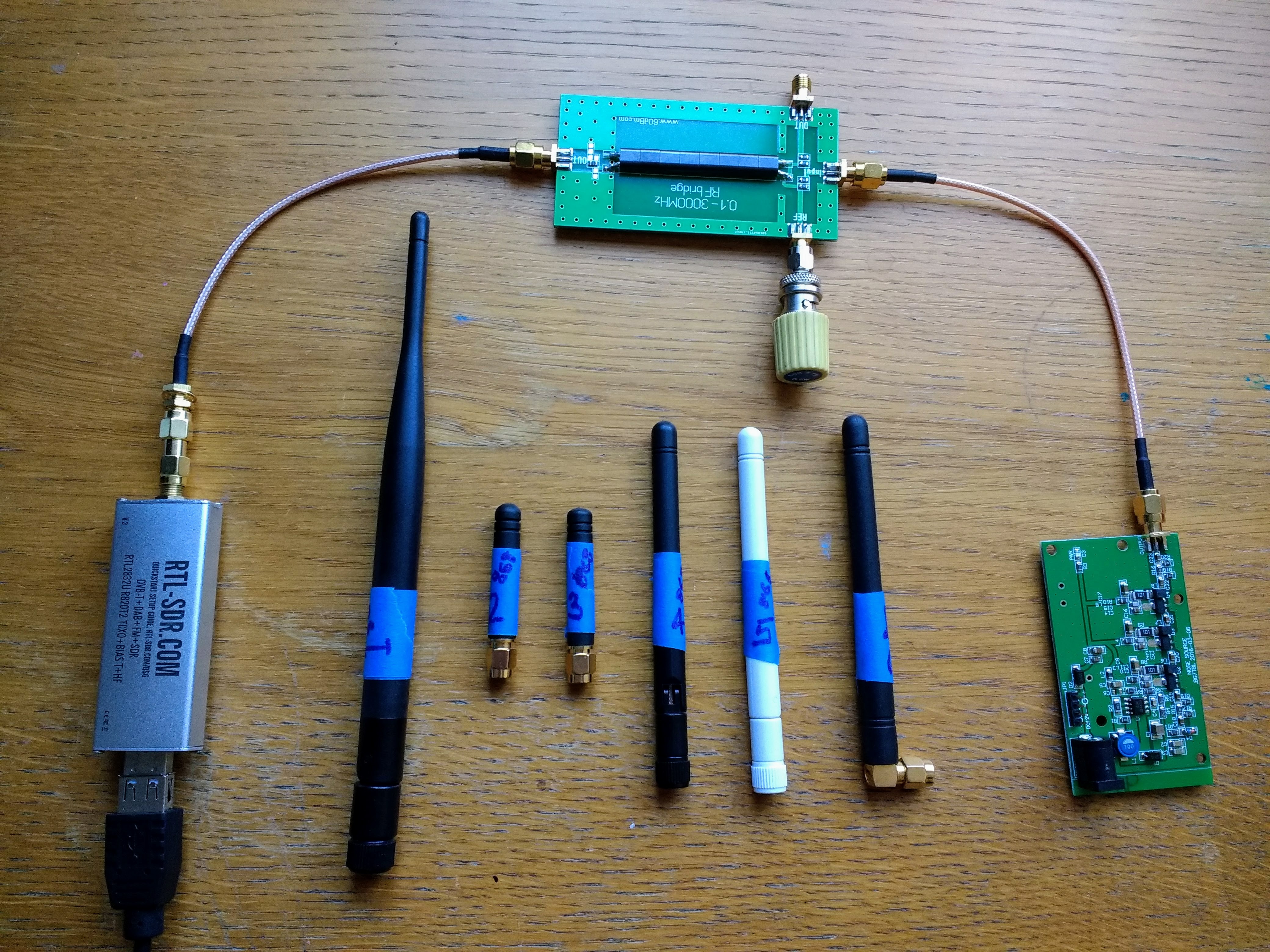
I ran a scan with no antenna attached as baseline and then attached each antenna in turn, producing a plot of scan - baseline, as below:
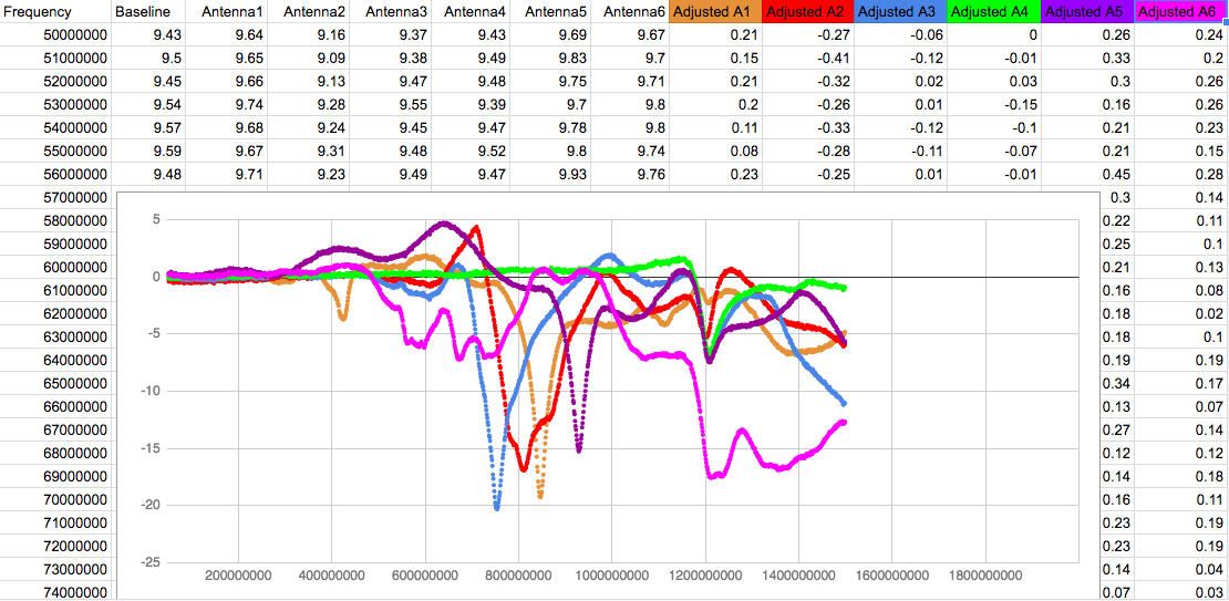
My question is - does this show that antennas 4 and 6 (green & pink) are not tuned for the 868MHz band?
Also, is there anything I can infer about the effectiveness of the remaining 4 antennae? - Thanks!
2 Likes
Just curious,
What exactly does the RF bridge do, how can this test an antenna?
White noise from 50MHz to 1.5GHz?
So, as far as I understand it and probably using incorrect technical terms. The bridge allows “balanced” connection of SDR to a broadband white noise source and the antenna “sinks” signal at its resonant frequency. The white noise source, I purchased off ebay - item 122922670429 also the RF bridge item 332052527822. The 50ohm load is something I acquired 30years ago from configuring 2BaseT ethernet over 50Ohm coax…
1 Like
Things in my test are getting more complicated that i was prepared for. I swapped two antennas, #8 (connected to Heltec) <-> #5 (connected to TTGOv2). It turns out that this improves the RSSI level of both boards:
- Heltec ~ +5-6 dBi
- TTGOv2 ~ +20 dBi !!
It’s not a real surprise that RF performance is an overall result of whole RF path {amplifier + pcb layout + cabling + antenna}, but i was suprised to see a delta of +20 dBi on the TTGOv2 using antenna #8 instead of #5, since both antennas have similar attributes, believing the datasheets (see above posting).
I’m not sure if it makes any sense to continue this test without proper professional measurement equipment. Probably we will see some more “good” and “bad” combinations, but this could all be highly specific to my setup.
Nevertheless it seems that the Siretta Delta 5A antenna is a good combination with TTGOv2.
Besides that, it turned out that there were no packets received from both boards between 15:27 an 16:48. Not sure what this caused. I don’t see a downtime of my internet line on my router. So causes could be the Wifi connection between gateway (MatchX) and router, some issue on the gateway itself, or with the TTN backend. Probably the Wifi? No, since in the same time no packets from my boards were received from another gateway, which i do not operate. So i assume a TTN backend issue.
PS: Thanks to Robin Meis for his TTNmon which i’m using for this test.
Heltec #8 -> #5
TTGOv2 #5 -> #8
I am about to carry out some tests on 868Mhz antennas myself, starting with a 1/4wave + radials as the reference. Whilst the use of a reflection bridge and noise source shown a few posts earlier gives an indication on antenna performance, it cannot tell us what will happen in real world situations.
The best antenna is one which radiates the maximum possible signal in the direction we want. For most TTN applications this direction will be close to the horizon. An antenna might be perfectly matched using ‘professional equipment’ but if the radiation is in a slightly upwards angle (which can happen with some antennas) then it will perform badly for a typical TTN application.
Antenna testing is easiest in a large flat area, I use my local playing fields. You need a transmitter on the frequency desired and some means of measuring signal strength. I have some small LoRa tracker boards that I can use for both, they have SMA sockets for the LoRa device for fitting antennas. The transmitter is programmed to send out short bursts of carrier. I can use another LoRa board with a SD1306 OLED connected as a signal strength meter.
Put the transmitter with test antenna on a pole\bamboo in the middle of the field and stand 50m or 100m away from the transmitter with the receiver. You should see the indicated RSSI peak, record the value. Change transmitter antenna and observe the RSSI that this antenna produces. The antenna with the lowest RSSI is the best one and you have measured the difference between them in dB. You can do much the same test by sending short LoRa test packets.
You can get closer to a real world situation by putting the test transmitter in the same position as your node or gateway and measuring the results standing some distance away.
2 Likes
You may be interested in some results of basic tests I did on the performance of a 868Mhz 1/4 vertical antenna with radials over the park today. I was using one RFM96 board for the transmitter and another for the reciever.
1/4 wave vertical with 4 x 1/4 radials at 45 degrees - 0dbm (reference)
1/4 wave vertical with 4 x 1/4 radials horizontal -1dbm
1/4 wave vertical with no radials -10dBm !!
So radials are very important.
As a referance test, which anyone could reproduce to test effectiveness of antennas and\or power output, if you use the above reference antenna on both transmitter and receiver, with the devices at shoulder height and 50M apart in an open field @ 2dBm power output the field strength readings\RSSI were;
RFM96 -64dBm
RF Exporer -67.5dBm
The above tests were with the antenna mounted direct to the module, I did also try with a 1M RG58 co-ax between antenna and module, that would unbalance the antenna and it look like it looses you around 5dB of signal.
Thank you for sharing these informations.
I can confirm that with a “spring chineese” antenna my 868MHz lora node does not work.
With a simple dipole antenna it works perfectly --> 8.7 km range tested
Ground plane seems to be extremly important 
dipole antenna is here : dipole antenna
JP
Indeed it does look like the green and pink plots belong to antenna’s that are not resonant around 700-900MHz. Maybe they are WiFi antenna’s.
I would open them and measure the inner dimensions of radiator and radials/sleeve, that would most likely show what frequency they were designed for…
The plot does not say much about the effectiveness of the other 4 antenna’s. If the impedance of an antenna is not close to 50 ohms it will not go deeper than the 15 to 20 dB you measured. But they can be perfect antenna’s for the designed frequency. The purple seems to be for 915MHz. The brown one seems to be the best for 868MHz.
Interesting how you generated the plots. I will try to reproduce the results here. I have the same hardware and also some mysterious antenna’s.
1 Like
Hi @costo, here is a link to the data - https://docs.google.com/spreadsheets/d/1lYxc-wYnOEiRWejV9VHWX5XTu1wWKWYz3R2zUfVvKFE/edit?usp=sharing
I used rtl_pan.exe which is a GUI front-end for rtl_power - I setup the scan frequency to be 50MHz to 1.5GHz then start - wait 5 seconds, stop, then wait for the scan to complete. Each scan produces a scan.csv with 1450 data points.
I based my spreadsheet on the first baseline scan (no antenna), then added a column for each antenna tested. Don’t bother trying this spreadsheet in Excel as it takes forever to load, just continue to use Google sheets.
I would be very interested to see your results and any further comments - thanks!
why this enormous range ? would 750 - 1050 (300 Mhz wide) be more inline and faster ?
I wanted to check for 433MHz antenna and I was just plain curious, using almost the full range of the SDR - it would have been really nice to check for resonance at 2.4GHz, but my SDR won’t go that far…
It is the opposite, the one with highest RSSI is best.
The RSSI is negative, so a lower ‘negative number’ (not lower RSSI) means it is higher, not lower. You are probably aware of this, but textually the statement is incorrect.
(How would an antenna with lower signal strength perform better? That is not logical.)
Your right of course.
I look at the numbers so often I tend to ignore the - part.
Interesting this
In English, it is generally accepted that the response is not affected by whether the question is in the affirmative or negative.
e.g. Do you have a car? … Yes (I have a car),
vs Don’t you have a car? …Yes (I have a car).
The answer is the same despite how the question is framed.
Most English people adjust this way, because usually, there is context and social cues which point to the gist of things. (not sure what the accepted culture norm would be elsewhere?)
However, those in England that insist on just the logical interpretation of a negative question are at risk of isolating themselves from an accepted social norm (the bane of those that are technically minded!).
As we know “signal strength” is measured in negative RSSI. so shouldn’t you say a lower signal strength is a lower RSSI (Because RSSI is a measure of signal strength?) (negative question joke intended)
I guess you could say both of you are correct - but one answer is more socially acceptable in a particular country - This why it is never a good thing to ask negative questions!
e.g. consider the concept of current flow - if you increase current, are you increasing or decreasing the flow of charge?
This is why it is always best to consider things in a “positive” manner 
just saying …
I have always liked Postel’s law, also known as the principle of robustness:
Be conservative in what you do, be liberal in what you accept from others.
From; IETF RFC793, Transmission Control Protocol, 1981.
Hi @pe1mew
I believe this is the antenna I have. Would you recommend creating a DIY one as linked The BIG and SMALL ANTENNA topic part 1 or say because I don’t have tools like a SWR meter to then check it with I’m better to keep with that one?
Which antenna are you referring to?
Without having an VNA (Vector Network Analyser) availabale and knowledge to operate it and experience in tuning these antennas I would not encourage anyone to build collinear antennas.
A VSWR meter needs a signal genarator to generate a continous signal of enough power so that the SWR meter can sense it. Our nodes will not generate aproperiate power for this purpose.
If you still want to build an antenna I propose the build a GP antenna. When you respect the dimensions it is likely that you have acceptabele results.
Hi @pe1mew, I was referring to the " VINNANT COL868/5-SCB" one from ebay at https://www.ebay.com/itm/302598573188 , As I have a 3D printer I was wondering about building one of the same design as I could use the rounding aid. However as I don’t have any analysing tools available I won’t plan on building one then.
1 Like