If you build a reference antenna such as the 1/4 vertical and radials on a N type chassis socket you can use that to compare against a co-linear. The reference antenna is an easy build and difficult to get wrong, it ought to have a predicatable behaviour.
You can then use this referance antanna to compare the performance of (and possibly tune) the co-linear, using a LoRa device as the signal generator (transmitter) and another LoRa device as a field strength meter.
Additions to the testing of a 1/4 vertical and radials;
1/4 wave vertical with 4 x 1/4 radials at 45 degrees - 0dbm (reference)
1/4 wave vertical with 4 x 1/4 radials horizontal -1dbm
1/4 wave vertical with 2 x 1/4 radials horizontal -3.5dbm
1/4 wave vertical with 1 x 1/4 radials horizontal -6dbm
1/4 wave vertical with no radials -10dBm !!
The above tests were with the antenna connected direct to the LoRa module that was the transmitter. Percieved wisdom is that adding a connecting cable will detune the antenna due the outer of the co-ax becoming part of the antenna, so the result below is a surprise;
1/4 vertical with 4 x 1/4 radials and 1m of RF58 co-ax connection for antenna 0dBm ?
i.e the 1m of co-ax did not appear to affect the preformance of the antenna as you might expect, but then the co-ax outer is in effect now part of the ground plane. .
Do I understand correctly that the results in the table are all from antenna directly mounted on the LoRa module, that you then did 2 additional measurements 1x with no radials and 1x with 4 radials with a 1m antenna cable between the LoRa module and antenna and then you did not see any difference (0dBm) between no radials directly mounted and connected via cable and also no difference between 4 radials directly mounted and connected via cable?
What antenna did you use for the LoRa module acting as receiver?
What was the distance between transmitter and receiver?
The difference between with and without radials is easily explained:
The ¼λ antenna without radials is a monopole. A monopole needs a proper groundplane to function properly. The one in your test does not have a proper groundplane.
While it is done often, it is actually not fair/reliable/realistic to compare the performance of (¼λ) monopole antenna’s without taking into account a proper corresponding groundplane.
Without a proper groundplane ¼λ monopoles will perform poorly by default.
The radials function as ground plane (so these antennas are actually variations on dipoles) which makes these antennas perform better. The number of radials and the angle will affect the antenna’s radiation pattern and performance. A non-uniform radiation pattern will make measurements position-dependent.
It would be interesting if you could include the results of a (vertically oriented) true ½λ dipole (2x ¼λ) in the comparison.
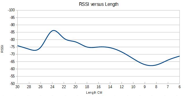
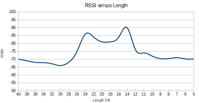
Here are some checks on the length of a vertical antenna, first with 4 x 1/4 radials then with no radials. As expected the output power peaks in the 8-9cm region for the antenna with radials. I will be testing some fine tuning in that region, to see if optimum length varies much between a selection of modules.
This time I was using a LoRa receiver as the field strength meter.
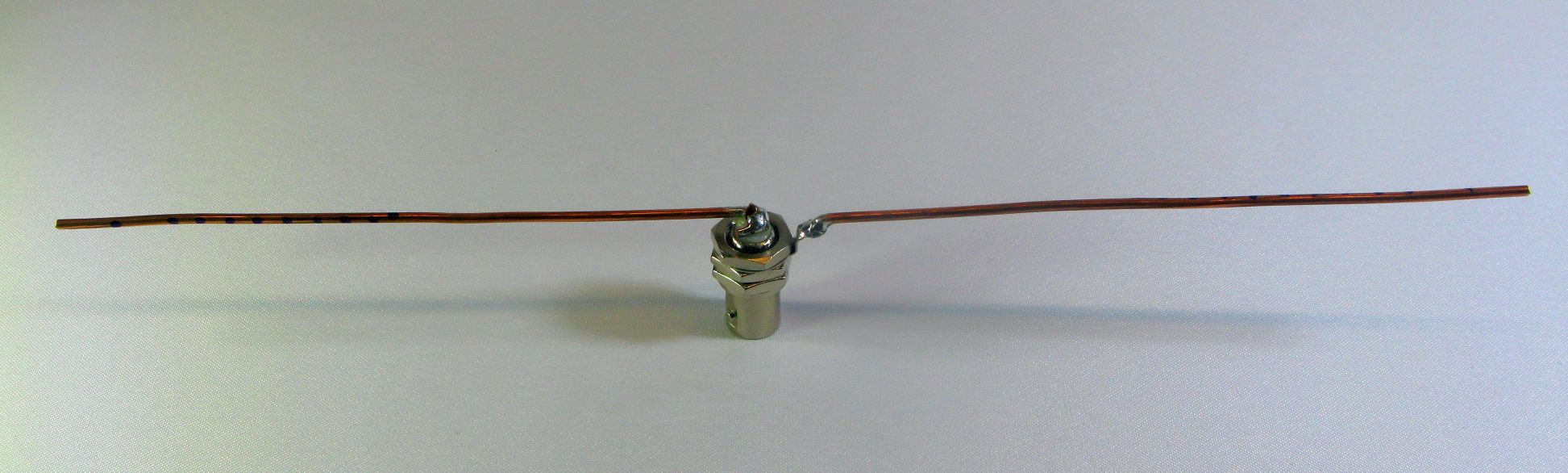
Built a simple dipole on the end of a BNC chassis socket, positioned it vertically and compared it to the referance 1/4 wave vertical with radials built on a N type chassis socket. Both antennas mounted direct on the LoRa module that was the transmitter.
With all elements the same length, 8.6mm, the dipole was 3dB down on the 1/4 wave vertical, not what you would expect.
I will have to run both antennas through a trim test to check if adjusting the element lengths for both antennas bring the performance closer together.
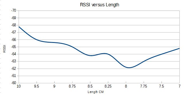
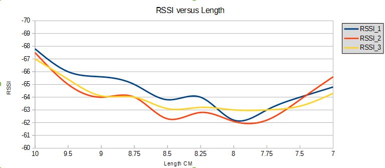
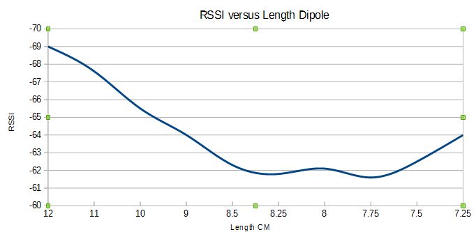
I tried triming the lengtrh of central vertcal of a 1/4 wave with radials. To see how the output varied with length, the result is below;
As you can see, for this module the radiated power of the antenna peaked at circa 7.95cm. The output at this length was some 2dB more than the theoretical optimum of 8.6cm. Also note how much the output varies for relativly small changes in element length.
2dB extra output may not seem a lot, but it represents around 25% extra distance.
I wonder if tuning the radial lengths maes the antenna it better or worse ?
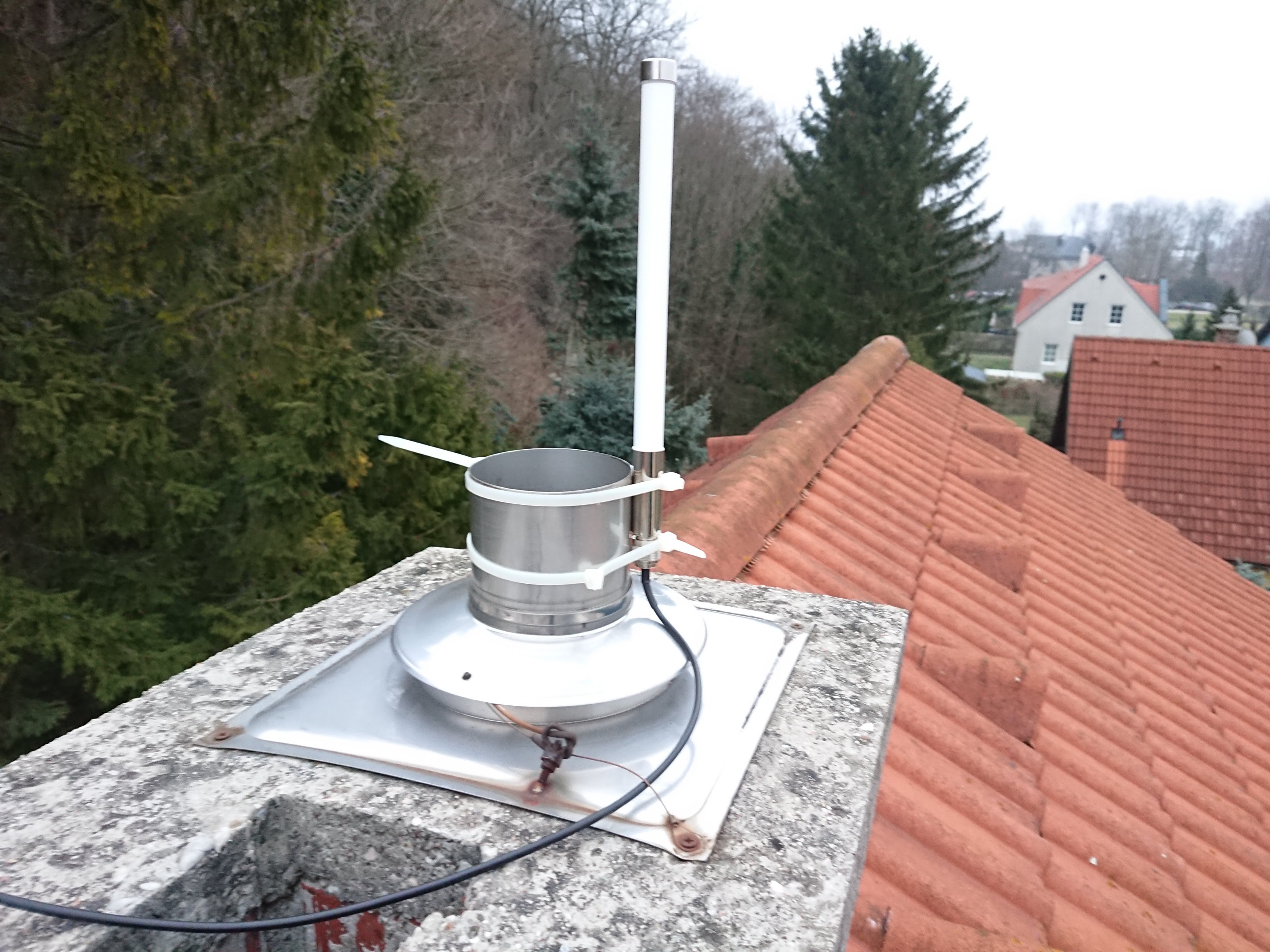
so… DELOCK 89583 in the house - well actually on it yet - though granted it’s a literally “quick fix” … any comments on how legit/effective it is to mount it that way? (the metal tube obviously goes down the whole chimney, ~9m - but there’s no oven connected anymore)
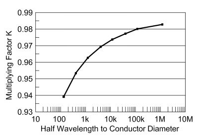
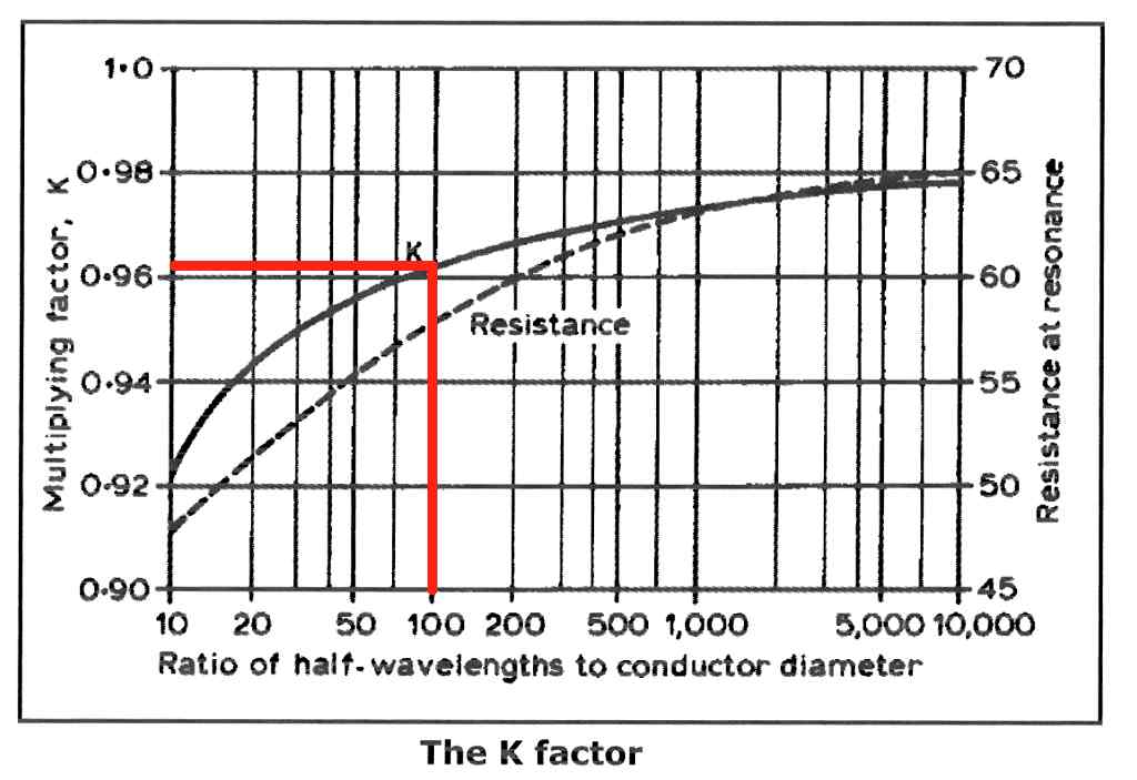
shows that when the wirediameter is 1.7 mm, the K factor for 100 is about 0.96 , so 4% shorter than expected.
The endeffect will make the k factor some more shorter.
Best is to measure your antenna with a reflection bridge for best VSWR and resonance.
Even those diagrams will not give you the ultimate solution.
Measuring in the lab can provide useful information, but my shed (lab) is way to small to be good for tuning antennas, due to presense of nearby objects, the metal roof etc.
By measuring out of doors you can eliminate the effect of nearby objects and test how the antennas will perform in realistic situations, a poor mans anechoic chamber if you like.
Please note that in your dipole design the coax feed is part of the antenna as well because there in no balun.
You might want to read this section of a Wikipedia article about dipoles.
Apologies for not mentioning it, there was no co-ax used to connect the dipole, it was mounted direct on the module, same as for the 1/4 wave vertical, keep it simple.
It was done this way specifically to avoid potential issues with the co-ax causing confusion etc.
I was also aware that with the theoretical impedance of the dipole being 75R if you chose to address this with baluns etc, it would significantly complicate the installation.
Yet despite all this, the ‘simple’ dipole performed as well and the more difficult to build 1/4 wave vertical with radials.