I also thought the same thing, until I saw the video. In the video you can clearly see that the wire does not stick to the former after he does the loop but it has a wider diameter.
In the end, it’s just a test with a piece of copper wire. I also have an N1201SA analyzer and callipers and I could try to fine tune the antenna.
I’ll also try your ⌀15 mm version as soon as possible (the wire with the loops is ready, I’m only waiting for the N-type connectors to arrive)
I form the coils and a section of one of those extensible fibreglass\carbon poles that you can uses for flags, antennas and rescuing things from trees.
The poles are tapered so somewhere in the set there is every size former from about 40mm to 2mm
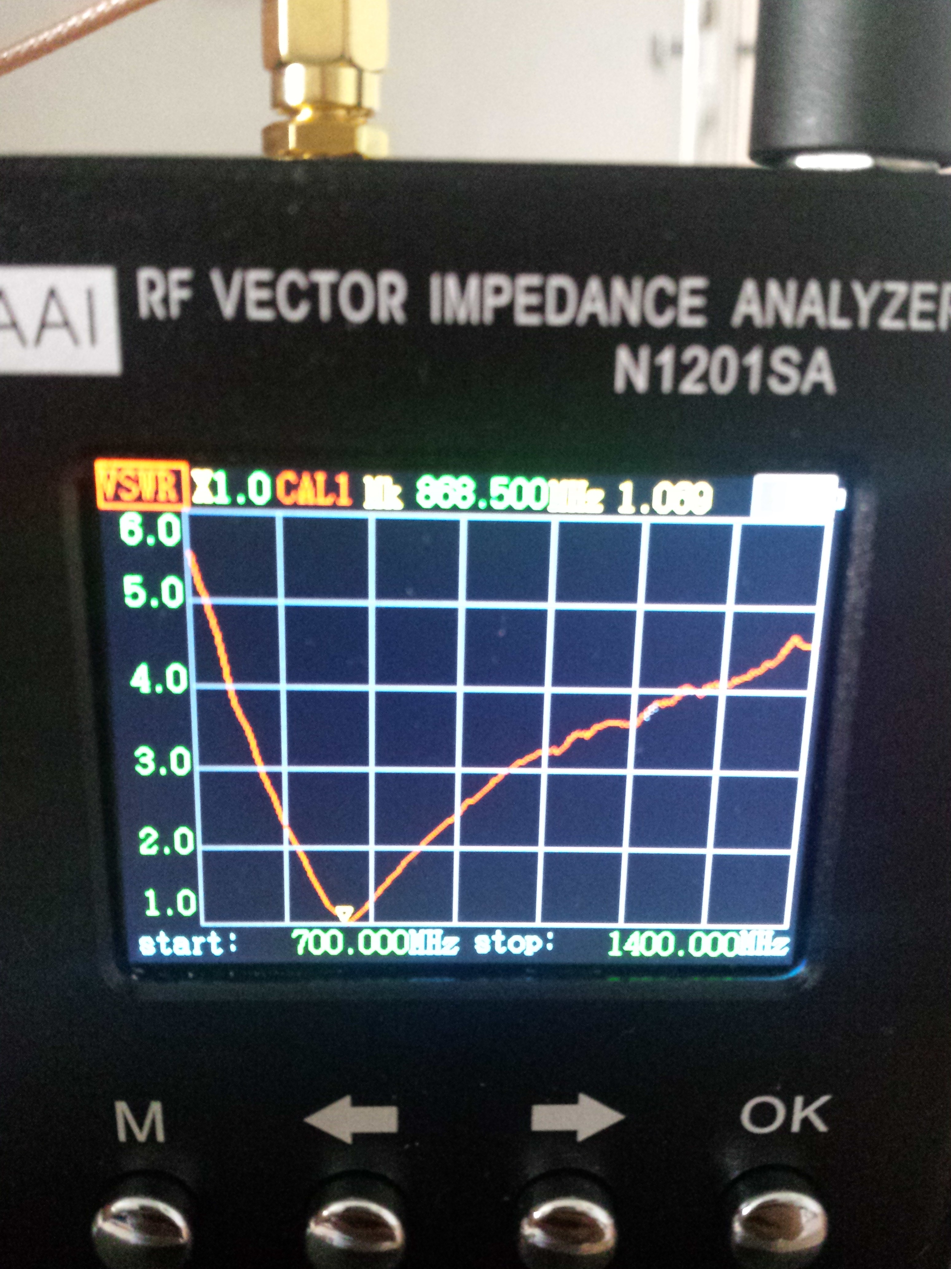
Generally speaking you are right, if you see a graph like kylix showed on that N1201SA, you do not know what radiation pattern that antenna has.
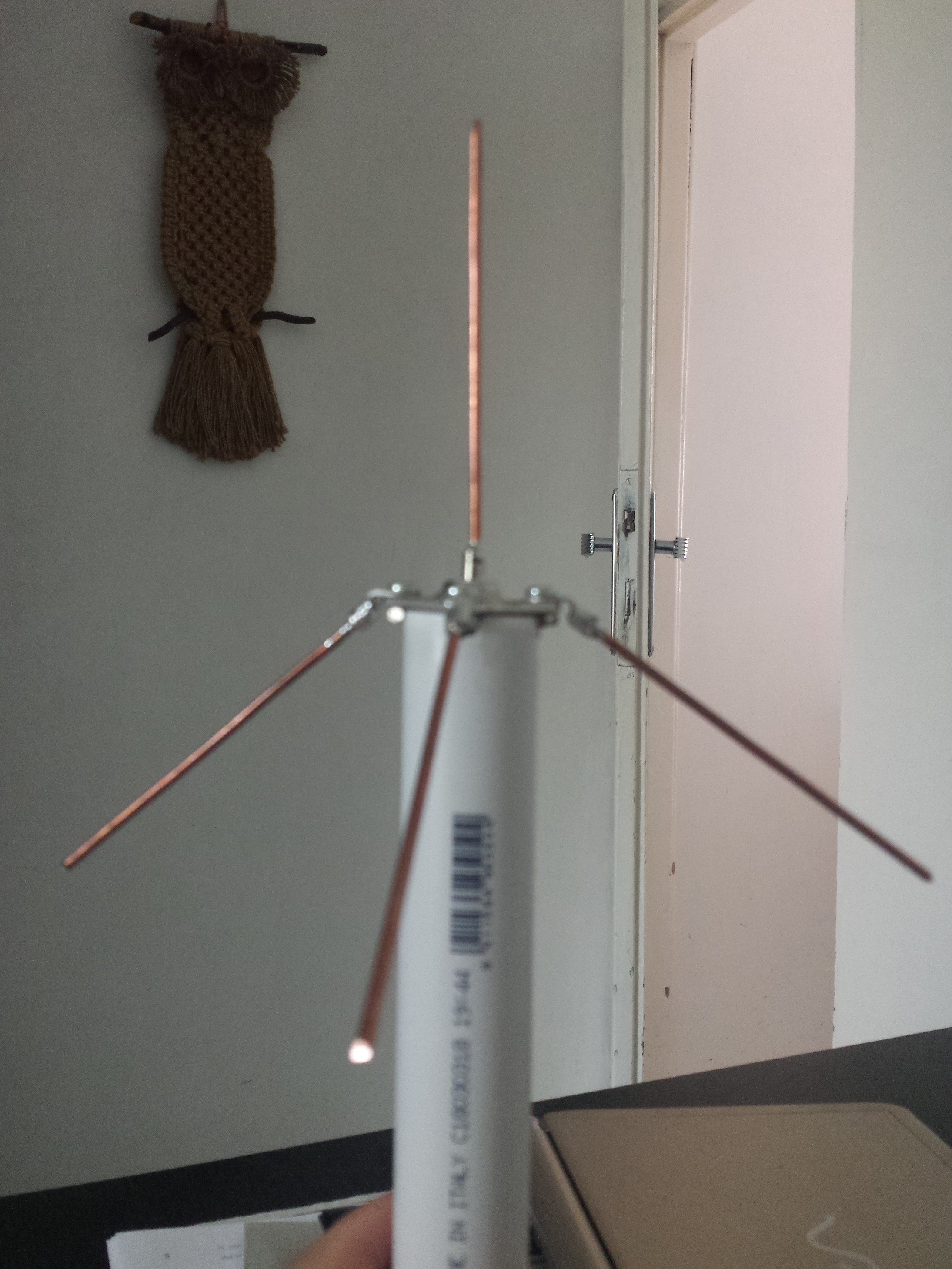
But we know more than just the graph, kylix made a picture of the antenna and it looks like a genuine GP.
A vertical resonant dipole is by definition a efficient radiator and has a gain of 2.15dBi* in the horizontal plane perpendicular to the dipole. A GP is almost as good, maybe the maximum is not exactly aimed to the horizon but a little bit skewed up to the sky. That would still mean a gain of >2.0dBi*.
I cut 3 small strips of expanded polystyreen (common package material) that I slided into the sleeve so that the coax cable stays centrally fixated inside the sleeve. Bending the antenna 90 degrees does not make any difference anymore, it stays tuned to 868MHz.
Sure, everything that reflects or absorbs EM-waves will influence the local field-strength. Usually in a unpredictable way.
But it will not influence the antenna radiation pattern, as that is measured in a anechoic chamber and is fixed for a given antenna.
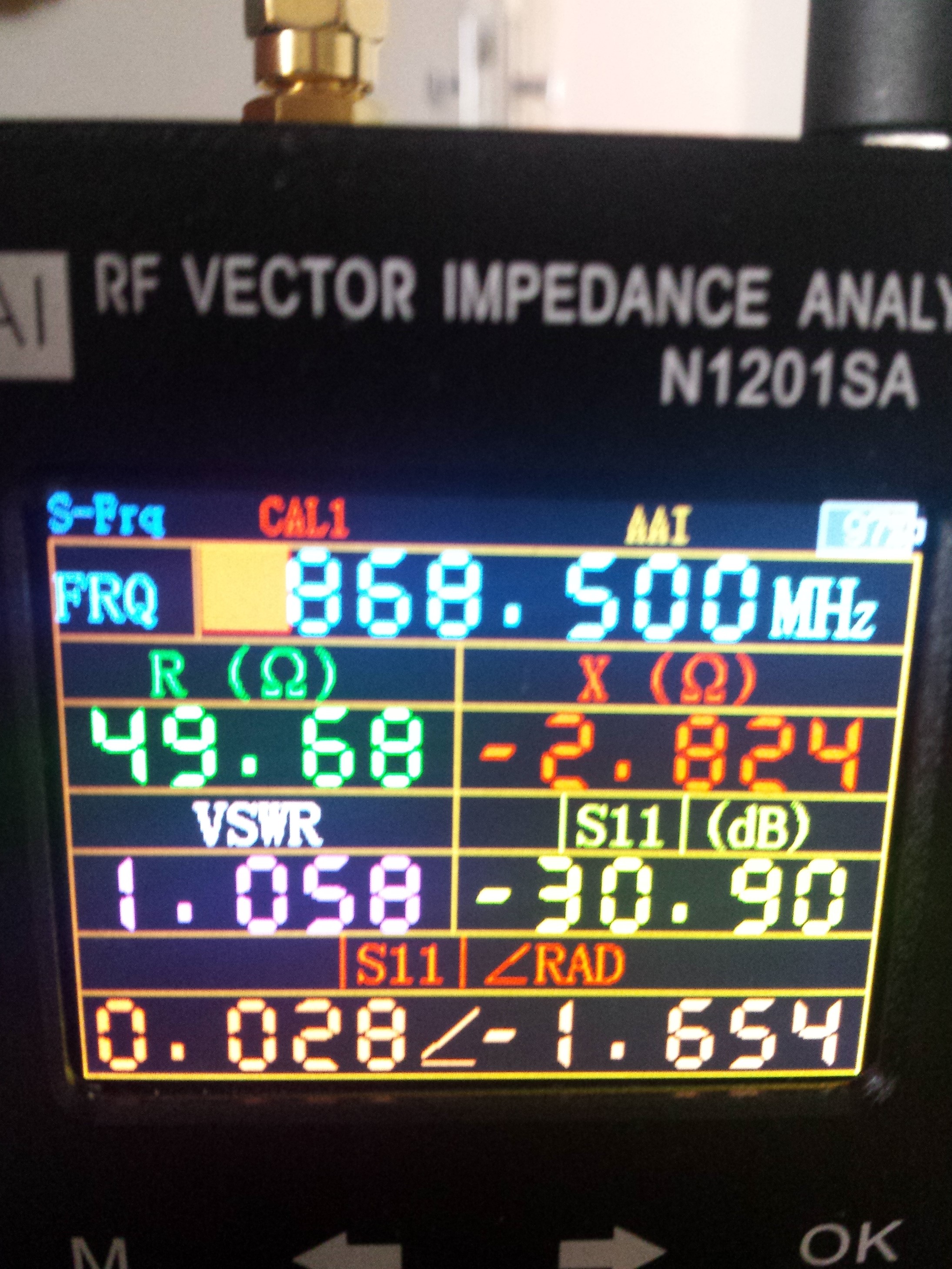
Just built one, and it comes out spot on 868Mhz, VWSR is 1.07.
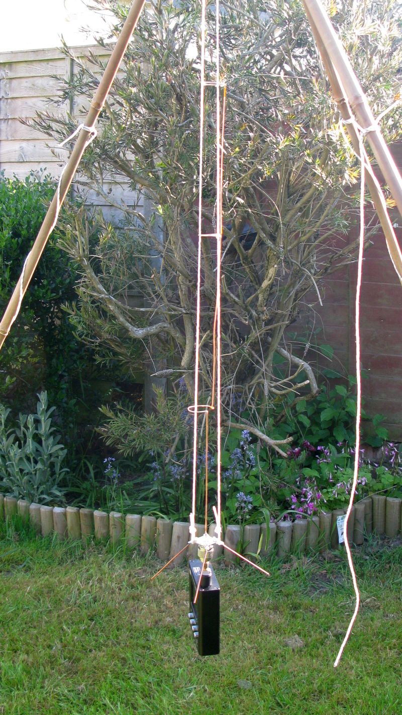
Measured gain in its bare state, 3.3dB over a 1/4wave with radials, so circa 5.3dBi.
However this antenna would need to be housed in a plastic tube or similar so I did some tests with plastic tubes over the antenna to simulate the real world use.
White plastic drainage pipe, OD 42.5mm, wall 2.5mm, VWSR 3.5, centre frequency 854Mhz
Grey plastic drainage pipe, OD 53.5mm, wall 1.5mm, VWSR 2.3, centre frequency 854Mhz
The conclusion would appear to be, that unless there is some form of magic pipe that does not affect the antenna, you may need to build it for a higher frequency so that when mounted in a weatherproof tube, it come down to the ‘right’ frequency.
Did you do the microwave test with the drainage pipes?
(cut small piece, put in microwave full nuke and look of it melts/burns/smokes etc, one of the above = no good)
So true. That why most antenna builders user very thing glasfiber tubes for that instead of PVC. But they are hard to find for consumers. But indeed the used materials will influence the antenna tuning, especially on these frequencies. (don’t get me started on 13 and 6 cm hamradio frequencies). Thats why I tune my antennas complete and preferably on location where they should be used.
If you change the gaps in the coils, from the design spec of 1.5mm, the antenna centre frequency rises.
So considering that the palstic tubes dropped the frequency by 1.6% I tuned the antenna upwards to 882Mhz, I ended up with a gap in the bottom coil of 10.5mm the middle one 7mm and the top one 7mm.
Putting the plastic tube over the antenna and testing again, the centre frequency was 868Mhz, VWSR of 1.15.
Will need to re-check the gain with the plastic tube in place, but I need to vist my local ‘anechoic’ test ground for that.