You can get fibreglass tubes of the right sort of diameter, 40mm or so, from the model rocket suppliers, not cheap though.
For the antenna I built the optimum tube would probably be some cheap plastic (so its very thin) but that has nice endcaps and solvent weld tube would then make assembly real easy.
If you can adjust the frequency of the antenna enough you ought to be able to make it work.
Just done that, the gain at 868Mhz appears to be about the same with the plastic tube in place, 3.5dB, when compared against the 1/4wave with radials.
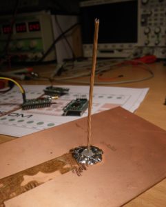
Shown is the reference antenna and the colinear in the tube, being compared. The test transmitter is the small green thing attached directly to the bottom of the antennas;
Great piece of work, thanks for sharing. Noticed the colinear has ground plane radials when connected to the analyser. Do you plan to keep the radials in the final installation? Was there a problem that caused you to add for testing?
To make the Colinear fit a smaller diameter plastic tube, has any one tried making smaller diameter loops? eg 2 turns at half the diameter and therefore the phasing loops maintain the same length of wire.
I am equally fascinated by this tread and all the testing and confused by my own hacked results. I have one node I used for low power testing based on @Charles’s low power pcb but as my sma connectors hadn’t landed in time I just soldered (I think!) 83mm of copper magnet wire, I guess about 1.25mm diameter directly to the pcb, just to avoid damaging the RFM 95 module. At SF7 I get easily 3.3km in a rural setting, reasonable line of site but that said my home (gateway/antenna) is not ideally placed. Similarly I made one of the home-brew ground plane antennas, roughly cut the antenna and gp wires (all just the solid core of some co-ax cable twisted together in a drill) to length and using this on a 1m cable to a pro-mini/rfm95 ball of wires I get over 21km at SF12.
My experience so far suggesting that the placement of any antenna has a far bigger bearing on its likelihood of working than it’s design or precise tuning. That said a lot of the junk from the far east is so badly out of spec…
That is true, placement and height give the greatest improvements.
But there are practical limits to the improvements you can gain in this way, and a properly tuned antenna will likley give you 50% to 100% more range than a ‘roughly cut’ one.
From the design of the antenna you built I assumed it was an end-fed colinear and as such didn’t need a ground plane (ie ground independent). Since this antenna is outside and subject to water/corrosion I’ve always had a preference to eliminate as many connections as possible and also eliminate penetrations through the antenna housing. Its for these reasons I was hoping this design would work without a ground plane. Anyway, nice bit of testing you performed.
I take your point, I was using the description in the video. Not sure why its described as a co-linear and I dont know the theoretical basis for its design. The coil spacings are at 50%, 70% and 54% of a wavelength.
Whatever, it very definetly needs a ground plane of some description, the lowest VWSR you get is 4.0 at 881Mhz.
@LoRaTracker, my vector analyser arrived so I repeated your tests on the ‘colinear’ antenna with the loops. Although I adjusted the dimensions for 915MHz, I obtained the exact same results. Yes, I agree it needs a ground plane!!! Built a simple 1/4 wave whip to prove the analyser is correct and obtained VSWR around 1.05 I’m looking for around 6dBi for a gateway antenna and not sure what to try next, a colinear from coax cable or a J-pole? Any thoughts.
I tried a slim jim and a jpole but at the adjustments of the matching section were quite difficult and I did not see much improvement over a 1/4wave with radials.
I’ve had another look at the antenna photo on the IRNAS site and there is a black item between the bottom of the antenna and the connector. It may simply be heatshrink, but it seems to reasonably long and larger diameter than the wire. I’m wondering if this is a Sleeve Balun to eliminate the need for radials. There is only documentation for the wire lengths and bending so the detail could be in the assembly instruction which aren’t published.
Hello to all
I can agree that cable length has a certain influence on VSWR. I experienced that already, when installing 3&4G GSM-antennas in a previous life, VSWR could be worsened or improved notably by leaving or cutting a few millimeters of the coax length. I was lucky enough to be working with Anritsu sitemasters then, but actually for LoRa development activities, I only use an N1201SA and it shows similar results for cable length influence.
I tested a cheap waterproof antenna like pe1mew in The BIG and SMALL ANTENNA topic part 1 , but also 2 long whip antennas from RAK Wireless and 4 short whip antennas from TTGO and Heltec, all for 868 MHz.
The waterproof antenna got about half a meter of cable fixed on it, so I had to use that anyway. But since this cable length is about 3 times the half-wavelength @868MHz, it should have only little influence on VSWR (but minus a few gain so not really ignored, Costo!). On testing indoors, I found very high VSWR’s due to reflexions of the walls. Once mounted outdoors on the roof, it showed quite good VSWR lower than 1.3,so I think this antenna is not so bad at all (@pe1mew: maybe this confirms BoRRoZ’s good results?).
Then I went for the whip antennas, and found that the fact of testing them indoors had little influence on any of them, as they all gave about the same VSWR indoors and outdoors. Two of them (a long RAK and a short TTGO whip) gave the lowest VSWR of 1.0 over a large band in the 868 range.
So I decided to test those two antennas, once mounted directly on the vector analyzer standing on a desk, then lying horizontally on the desk, and finally mounted on a stand and sequencially tested with cable extenders of 25, 17 ,16 and 15 cm. You have to add about 2x1 cm to the cable length if you count it strictly from pin to pin, so only the 15 cm extender cable got around the half wave length of 17,27 cm… and this makes sense, as all cables gave VSWR between 2,3 to 6 and more when using the extensions, except the 15 cm extension which got 1.7 VSWR !
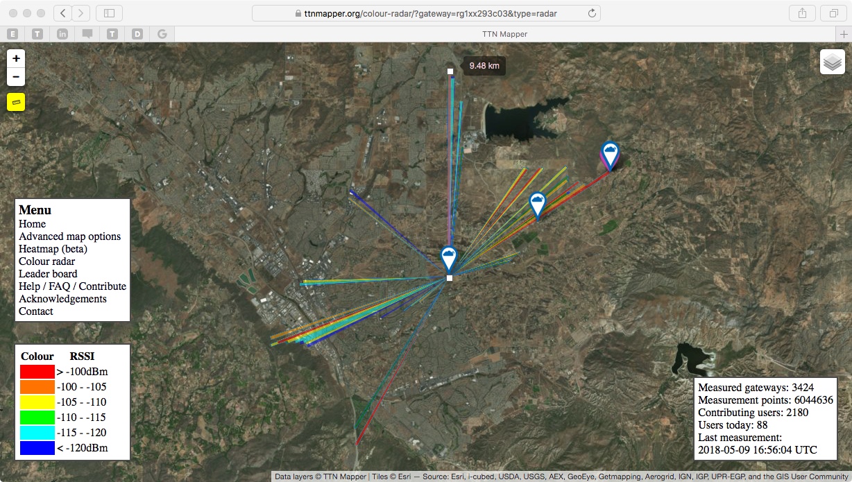
We just placed our 3rd gateway in Temecula wine country. The antenna is a 6 dBi omnidirectional installed on the roof of the winery. TTN mapper shows 9.5 km range, and we could probably get more with stations placed at high locations. We tested range with the gateway indoors, just got a few blocks away. Big improvement!
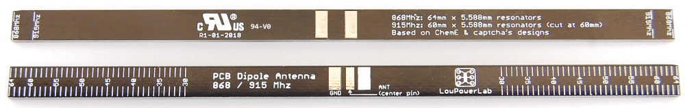
You may also use a very easy to build antenna, that provides ~2dB gain, while being electrically short cutted, which increases parasitic rejection: The J-Pole antenna. You may ust this calculator to determine the dimensions: http://hamuniverse.com/jpole.html
At 867 MHz your antenna will be ~25cm long and will fit into a 16mm electrical plastic conduit.
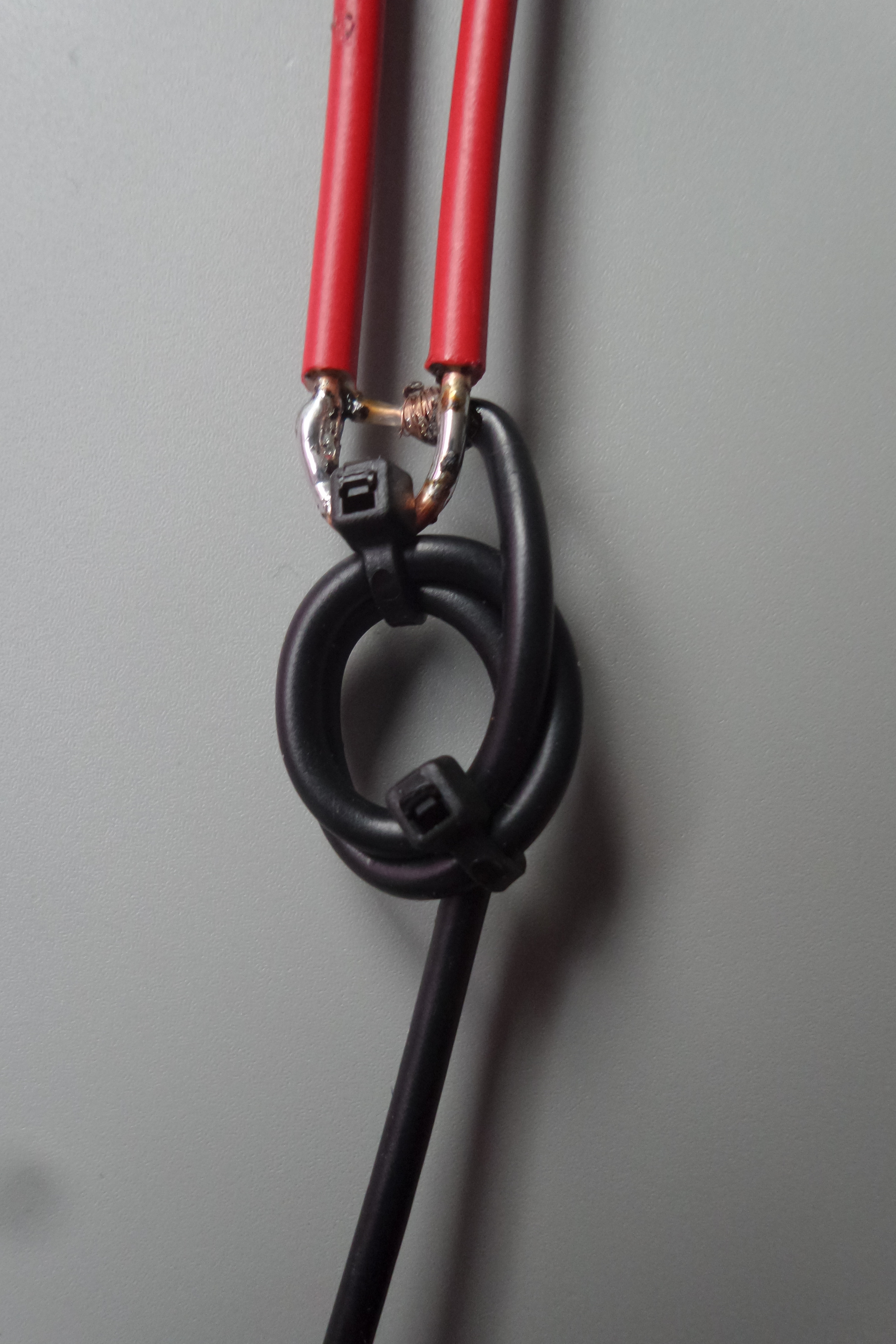
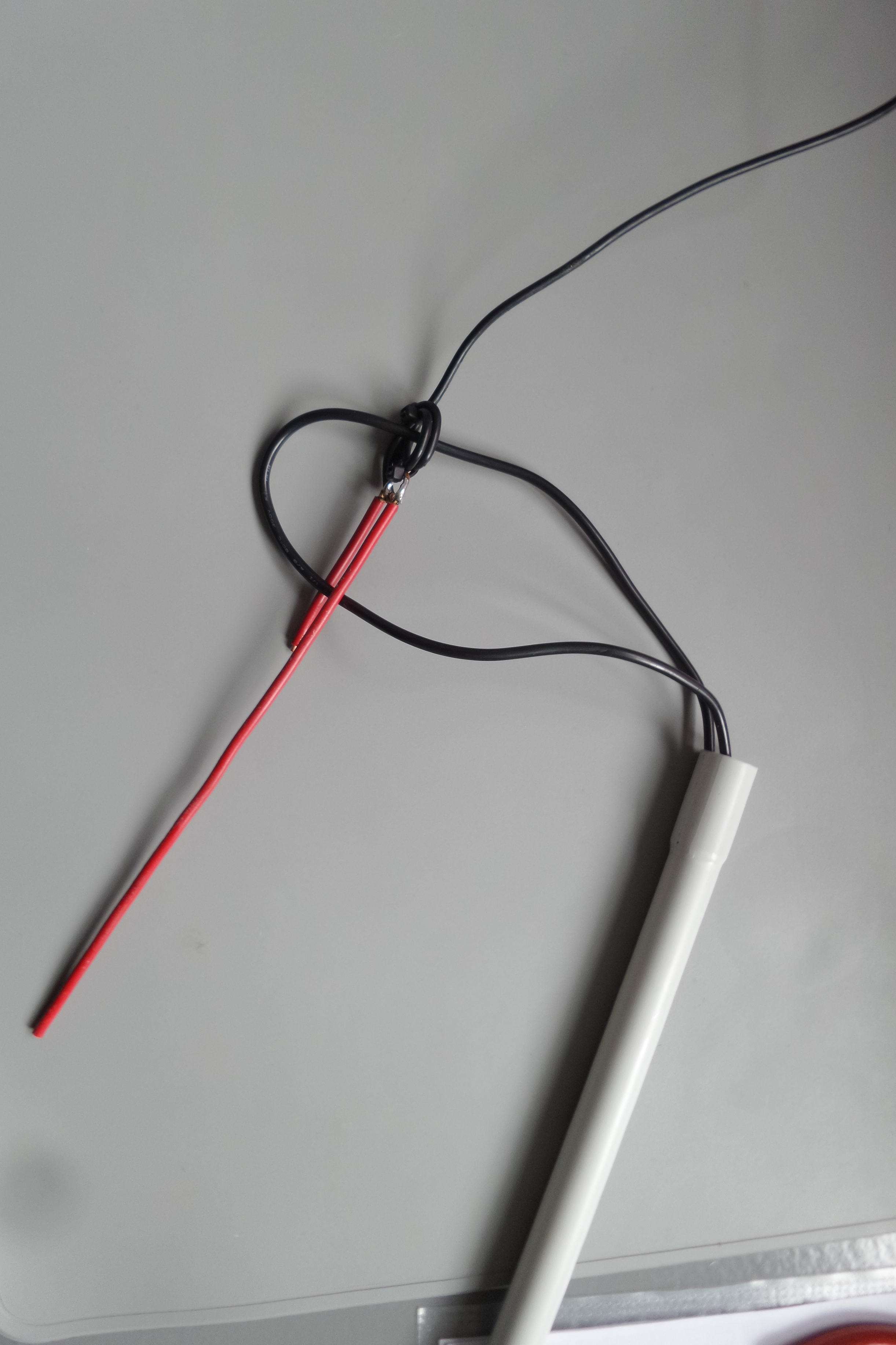
At the base of the antenna I have winded 3 loops of the coax cable to symmetrize the signal (balun).
The antenna is built in minutes…In the last picture the black wire loop was just used transiently to pull the antenna into the plastic conduit without staining the balun loops.