@paulb, what software are you running on your node, I have struggled with the esp8266
1 Like
@Amedee i got it running, thank you very much for the integration of collectd to the resin.io ttn gateway setup! Even encryption for transmitting the data per udp is working - just one little question: where do you get the supply voltage from in your screenshot from grafana? Per collectd? How? Thank you very much!
Cool!
You need some additional hardware to read the supply voltage…
I am using @dbrgn backplane which has a Sensirion SHT21 for temperature/humidity and a Microchip MCP3425 for the voltage.
When you set GW_BACKPLANE=DBRGN in resin.io , the run script of the Collectd container will enable 2 Python Collectd plugins to pass the data to Collectd.
Plugins ‘source’ is available here
1 Like
Ahh thx for the info, my gateways are build on the pcb from @Charles (c2h), so i have to build something on my own to measure the voltage.

6 Likes
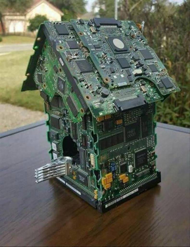
What a pity of all that gold. 
1 Like
Well, that is a valueable home
1 Like
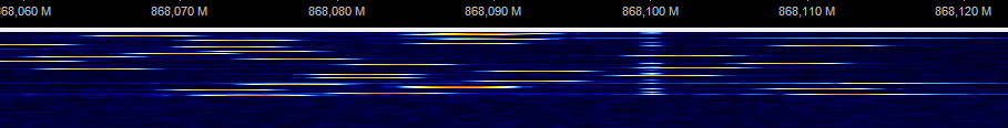
Sniffing Lora with a cheap RTL-SDR dongle
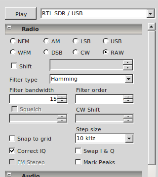
The screencast was taken with a bandwidth of 7.8 kHz CR 4/5 and SF12
6 Likes
what app did you use?
could you please also publish the parameters used for your sample?
thanks!
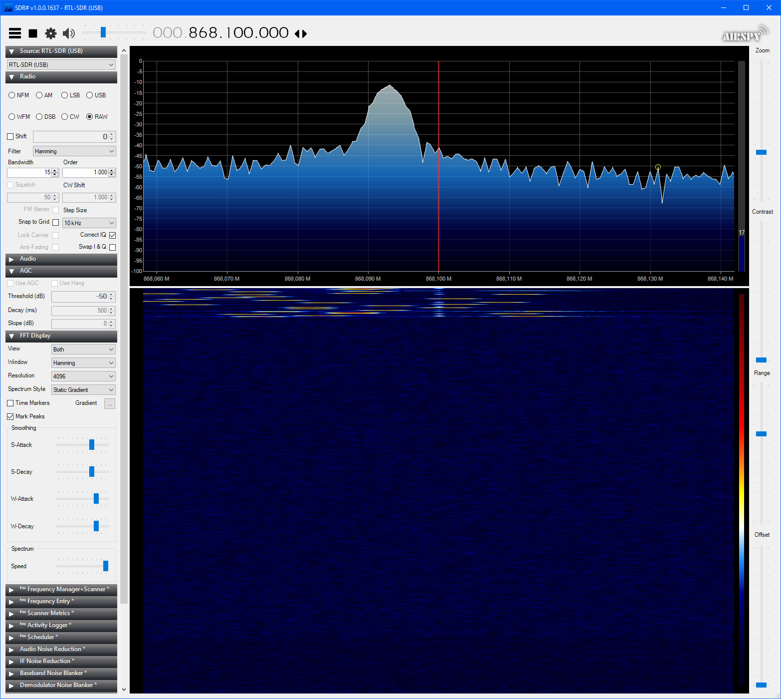
A pity with a cheap RTL-SDR dongle and a program like SDR# (SDRsharp) is that the full LoRaWAN spectrum (868MHz at least) is not completely visible at once on the screen. So when it hops to a different channel that frequency may be off screen.
It is not possible to zoom out far enough to make all channels visible onscreen.
This is probably a limitation of the RTL-SDR dongle I assume(?).
@ursm The application is SDR # (SDRSharp) like bluejedi has already been noticed.
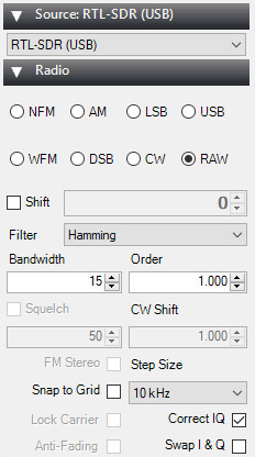
About the parameters:
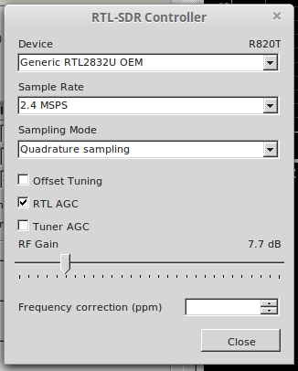
For the controller (dongle)
From the Radio drop-down menu
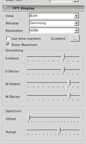
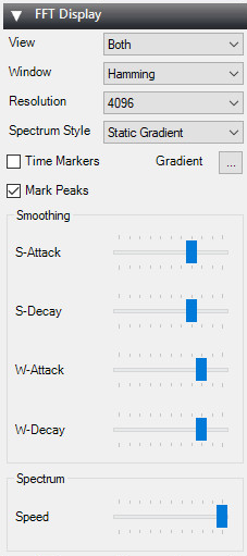
And the FFT Display
Does this answer your questions ?
2 Likes
My pictures look very different. Any idea why (did I miss some settings)?
Your SDR# shows version v0.0.0.0 (v0.0 really?) and your UI (dialogs) look different.
The version that I used is: v1.0.0.1637 (on Windows 10).
Below some pictures:
(The pictures were automatically downsized while uploading. I don’t know why they cannot be clicked for full size and why they do not show the file name.)
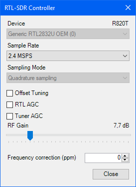
AGC disabled
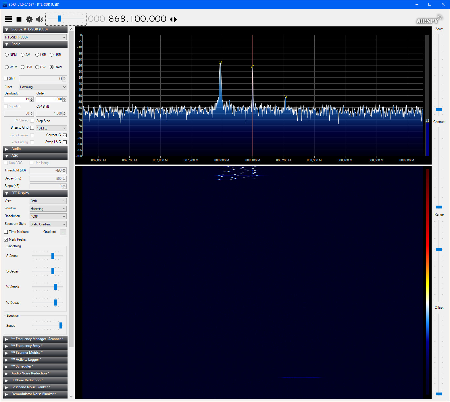
With AGC disabled (lower noise floor) and more zoomed out.
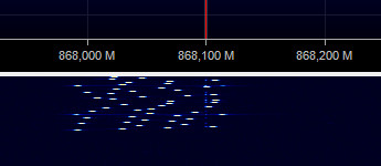
With AGC disabled (lower noise floor) and more zoomed out (partial).
Added because full picture cannot be maximized.
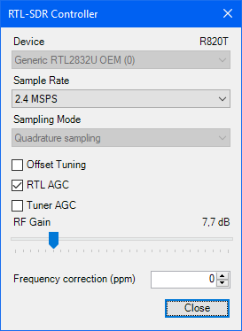
RTL AGC enabled
With RTL AGC enabled (higher noise floor) and more zoomed in.
With RTL AGC enabled (higher noise floor) and more zoomed in (partial)
Added because full picture cannot be maximized.
More partial pics (because the full pictures cannot be maximized):
I am running sdrsharp on my Linux computer, that makes the difference in the user interface and is probably the reason for the strange version number.
For the sample i didn’t used a LoraWAN package. I used a very low bandwith 7.8 kHz and the highest sprading factor sf12.
You can use this sketch with a Pro mini and a RFM95.
/*
 *  Version:           1.0.1
 *  Design:            Clemens
 *
 ***************************************************************************************
 * Channel CH1 868.100 MHz
 * Channel CH2 868.300 MHz
 * Channel CH3 868.500 MHz
 * Channel CH4 867.100 MHz
 * Channel CH5 867.300 MHz
 * Channel CH6 867.500 MHz
 * Channel CH7 867.700 MHz
 * Channel CH8 867.900 MHz
 * Channel CH9 869.525 MHz
****************************************************************************************/

#include <SPI.h>

/*------------ REGISTERS -------------*/
#define RegFifo               0x00
#define RegOpMode             0x01
#define RegFrfMsb             0x06
#define RegFrfMid             0x07
#define RegFrfLsb             0x08
#define RegPaConfig           0x09
#define RegLna								0x0C
#define RegFifoAddrPtr        0x0D
#define RegFifoTxBaseAddr     0x0E
#define RegFifoRxBaseAddr     0x0F
#define RegFifoRxCurrentAddr  0x10
#define RegIrqFlags           0x12
#define RegRxNbBytes          0x13
#define RegPktSnrValue        0x19
#define RegPktRssiValue       0x1A
#define RegModemConfig1       0x1D
#define RegModemConfig2       0x1E
#define RegModemConfig3       0x26
#define RegSymbTimeoutLsb     0x1F
#define RegPreambleMsb        0x20
#define RegPreambleLsb        0x21
#define RegPayloadLength      0x22
#define RegModemConfig3       0x26
#define RegInvertIQ           0x33
#define RegSyncWord           0x39

/*--------- DIO mapping --------------*/
#define RegDioMapping1        0x40
#define RegDioMapping2        0x41
// DIO function mappings               D0D1D2D3
#define RXDONE                0x00  // 00------
#define TXDONE                0x40  // 01------
#define RXTOUT                0x00  // --00----

/*--------- RegOpMode ---------------*/
#define MODE_SLEEP            0x00
#define MODE_STANDBY          0x01
#define MODE_TX               0x03
#define MODE_RXSINGLE         0x06
#define MODE_RXCONTINUOUS     0x05
#define MODE_LORA             0x80

/*--------- IRQ Flags --------------*/
#define TX_DONE               0x08
#define VALID_HEADER          0x10
#define PAYLOAD_CRC_ERROR     0x20
#define RX_DONE               0x40
#define RX_TIMEOUT            0x80

const uint8_t RFM_SS = 10;
const uint8_t DIO0 = 2;

enum OpMode {SLEEP, LORA, STANDBY, TX, RXSINGLE, RXCONTINUOUS};
enum SpreadingFactor {SF7, SF8, SF9, SF10, SF11, SF12};
enum Channel {CH1, CH2, CH3, CH4, CH5, CH6, CH7, CH8, CH9};
enum Bandwidth {KHZ_7_8,KHZ_10_4,KHZ_62_5,KHZ_125, KHZ_250, KHZ_500};
enum CodingRate {CR4_5, CR4_6, CR4_7, CR4_8};
enum HeaderMode {EXPLICIT, IMPLICIT};

uint8_t dataTx[3];
uint8_t dataLenTx = 3;

// PayloadCrcError
bool CRC = true;
// set Low Data Rate Optimization true
bool LDR = true;
// set one Bandwidth (KHZ_7_8,KHZ_10_4,KHZ_62_5,KHZ_125, KHZ_250, KHZ_500)
Bandwidth bw = KHZ_7_8;
// set coding rate (CR4_5, CR4_6, CR4_7, CR4_8)
CodingRate cr = CR4_5;
// set header mode (EXPLICIT, IMPLICIT)
HeaderMode hm = EXPLICIT;
// set spreading factor (SF7, SF8, SF9, SF10, SF11, SF12)
SpreadingFactor sf = SF12;

// preamble length in symbols
uint16_t preamble = 8;

void setup() {
  SPI.begin();

  pinMode(RFM_SS, OUTPUT);
  digitalWrite(RFM_SS, HIGH);

  initRFM();
  initModemConfig(bw, cr, hm, sf, CRC, LDR);
  setPreamble(preamble);

}

void loop() {


  dataTx[0] = 0x00;
  dataTx[1] = 0xFF;
  dataTx[2] = 0x00;


  sendData(dataTx, dataLenTx);

  delay(30000);

}

/*****************************************************************************************
* initialize the RFM module
*****************************************************************************************/
void initRFM(void) {

	//set RFM to sleep
	setOpMode(SLEEP);

  	//Set RFM in LoRa mode
	setOpMode(LORA);

  	//Set RFM in Standby mode wait on mode ready
	setOpMode(STANDBY);
  delay(10);

	//Set carrier frequency
	setChannel(CH1);

	//PA pin (maximal power)
  writeReg(RegPaConfig, 0xFF);

	//Switch LNA boost on High Frequency (RFI_HF) LNA current adjustment Boost on, 150% LNA 		current, LNA gain setting:G1 = maximum gain
  writeReg(RegLna,0x23);

  //Set LoRa sync word
  writeReg(RegSyncWord, 0x34);

  //Set IQ to normal values
	writeReg(RegInvertIQ, 0x27);
}
/****************************************************************************************
* Description : initialize the modem configuration
* Argument 1 : Bandwidth (KHZ_7_8,KHZ_10_4,KHZ_62_5,KHZ_125, KHZ_250, KHZ_500)
* Argument 2 : CodingRate (CR4_5, CR4_6, CR4_7, CR4_8)
* Argument 3 : HeaderMode (EXPLICIT, IMPLICIT)
* Argument 4 : SpreadingFactor (SF7, SF8, SF9, SF10, SF11, SF12)
* Argument 5 : bool payload CRC error check ON or OFF
* Argument 6 : bool low data rate optimize ON or OFF
****************************************************************************************/
void initModemConfig(Bandwidth bw, CodingRate cr, HeaderMode hm, SpreadingFactor sf, bool CRC, bool LDR) {
	//set modem configuration
	setConfig1(bw, cr, hm); // 7,8 kHz 4/5 coding rate explicit header mode
	setConfig2(sf, CRC);    // SF12 CRC ON
	setConfig3(LDR);        // LowDataRateOptimize ON, AGC auto ON
}
/**************************************************************************************
* Description : set the preamble value
* Argument 1  : uint16_t the value of the preamble (+4)
**************************************************************************************/
void setPreamble(uint16_t value) {

  uint8_t msb = value >> 8;
  uint8_t lsb = value;

	writeReg(RegPreambleMsb, msb);
	writeReg(RegPreambleLsb, lsb);
}

/*****************************************************************************************
* Description : switch to receive
*****************************************************************************************/
void initRx(void) {

  //Change DIO 0 to RxDone
  writeReg(RegDioMapping1, RXDONE);

  //Switch to continuous receive
  setOpMode(RXCONTINUOUS);
}
/*****************************************************************************************
* Description : Function for sending a package with the RFM
* Argument 1  : array pointer to data that will be send
* Argument 2  : data lenght
*****************************************************************************************/
void sendData(uint8_t *data, uint8_t len) {

  //Switch DIO0 to TxDone
  writeReg(RegDioMapping1, TXDONE);

  // initialize the payload size and address pointers
  writeReg(RegFifoTxBaseAddr, 0x00);
  writeReg(RegFifoAddrPtr, 0x00);

  //Set payload length to the right length
  writeReg(RegPayloadLength, len);

  //Write Payload to FiFo
  writeBuffer(RegFifo, data, len);

  //Switch RFM to Tx
  setOpMode(TX);

}

/*****************************************************
* Description: clear the IRQ flags
*****************************************************/
void clearIRQ(void) {
  //Clear interrupt register
  writeReg(RegIrqFlags,0xFF);
}

/*****************************************************
* Description : write Register
* Argument 1  : address
* Argument 2  : data
*
*****************************************************/
void writeReg(uint8_t addr, uint8_t data) {
  digitalWrite(RFM_SS, LOW);
  //Send Addres with MSB 1 to make it a write command
  SPI.transfer(addr | 0x80);
  SPI.transfer(data);
  digitalWrite(RFM_SS, HIGH);
}

/*****************************************************
* Description : read Register
* Argument    : address
* Return      : data
******************************************************/
uint8_t readReg(uint8_t addr) {

  uint8_t data;
  digitalWrite(RFM_SS, LOW);
  //Send Addres with MSB 0 to make it a read command
  SPI.transfer(addr & 0x7F);
  // Send 0x00 to be able to receive the answer from the RFM
  data = SPI.transfer(0x00);
  digitalWrite(RFM_SS, HIGH);

  return data;
}

/*****************************************************
* Description: write to FIFO buffer
*
*****************************************************/
void writeBuffer(uint8_t addr, uint8_t buf[], uint8_t len) {

  digitalWrite(RFM_SS, LOW);
  //Send Addres with MSB 1 to make it a write command
  SPI.transfer(addr | 0x80);
  SPI.transfer(buf, len);
  digitalWrite(RFM_SS, HIGH);
}

/*****************************************************
* Description: read from FIFO buffer
*
*****************************************************/
void readBuffer(uint8_t addr, uint8_t buf[], uint8_t len) {
  digitalWrite(RFM_SS, LOW);
  //Send Addres with MSB 0 to make it a read command
  SPI.transfer(addr & 0x7F);
  for (uint8_t i = 0; i < len; i++) {
    buf[i] = SPI.transfer(0x00); // Send 0x00 to be able to receive the answer from the RFM
  }
  digitalWrite(RFM_SS, HIGH);
}
/************************************************
* Description : set opMode
* Arguments   : Enum OpMode SLEEP, LORA, STANDBY, TX, RXSINGLE, RXCONTINUOUS
*
*************************************************/
void setOpMode(OpMode mode) {
	switch(mode) {
		case SLEEP:
			writeReg(RegOpMode, MODE_SLEEP);
			break;
		case LORA:
			writeReg(RegOpMode, MODE_LORA);
			break;
		case STANDBY:
			writeReg(RegOpMode, (MODE_LORA | MODE_STANDBY) );
			break;
		case TX:
			writeReg(RegOpMode, (MODE_LORA | MODE_TX) );
			break;
		case RXSINGLE:
			writeReg(RegOpMode, (MODE_LORA | MODE_RXSINGLE) );
			break;
		case RXCONTINUOUS:
			writeReg(RegOpMode, (MODE_LORA | MODE_RXCONTINUOUS) );
			break;
	}
}
/************************************************
* Description : set coding rate and header @ Bandwidth 125 kHz
* Argument1   : Enum Bandwidth KHZ_125, KHZ_250,
* Argument2   : Enum CodingRate CR4_5, CR4_6, CR4_7, CR4_8
* Argument3   : Enum HeaderMode EXPLICIT, IMPLICIT
*************************************************/
void setConfig1(Bandwidth bw, CodingRate cr, HeaderMode headerMode) {
		if (bw == KHZ_500) {
		switch (cr) {
			case CR4_5:
				if (headerMode == EXPLICIT) {
					writeReg(RegModemConfig1, 0x92); //500 kHz 4/5 coding rate explicit header mode
				} else {
					writeReg(RegModemConfig1, 0x93); //500 kHz 4/5 coding rate implicit header mode
				}
				break;
			case CR4_6:
				if (headerMode == EXPLICIT) {
					writeReg(RegModemConfig1, 0x94); //500 kHz 4/6 coding rate explicit header mode
				} else {
					writeReg(RegModemConfig1, 0x95); //500 kHz 4/6 coding rate implicit header mode
				}
				break;
			case CR4_7:
				if (headerMode == EXPLICIT) {
					writeReg(RegModemConfig1, 0x96); //500 kHz 4/7 coding rate explicit header mode
				} else {
					writeReg(RegModemConfig1, 0x97); //500 kHz 4/7 coding rate implicit header mode
				}
				break;
			case CR4_8:
				if (headerMode == EXPLICIT) {
					writeReg(RegModemConfig1, 0x98); //500 kHz 4/8 coding rate explicit header mode
				} else {
					writeReg(RegModemConfig1, 0x99); //500 kHz 4/8 coding rate implicit header mode
				}
				break;
		}
	} else if (bw == KHZ_250) {
		switch (cr) {
			case CR4_5:
				if (headerMode == EXPLICIT) {
					writeReg(RegModemConfig1, 0x82); //250 kHz 4/5 coding rate explicit header mode
				} else {
					writeReg(RegModemConfig1, 0x83); //250 kHz 4/5 coding rate implicit header mode
				}
				break;
			case CR4_6:
				if (headerMode == EXPLICIT) {
					writeReg(RegModemConfig1, 0x84); //250 kHz 4/6 coding rate explicit header mode
				} else {
					writeReg(RegModemConfig1, 0x85); //250 kHz 4/6 coding rate implicit header mode
				}
				break;
			case CR4_7:
				if (headerMode == EXPLICIT) {
					writeReg(RegModemConfig1, 0x86); //250 kHz 4/7 coding rate explicit header mode
				} else {
					writeReg(RegModemConfig1, 0x87); //250 kHz 4/7 coding rate implicit header mode
				}
				break;
			case CR4_8:
				if (headerMode == EXPLICIT) {
					writeReg(RegModemConfig1, 0x88); //250 kHz 4/8 coding rate explicit header mode
				} else {
					writeReg(RegModemConfig1, 0x89); //250 kHz 4/8 coding rate implicit header mode
				}
				break;
		}
	} else if (bw == KHZ_125) {
		switch (cr) {
			case CR4_5:
				if (headerMode == EXPLICIT) {
					writeReg(RegModemConfig1, 0x72); //125 kHz 4/5 coding rate explicit header mode
				} else {
					writeReg(RegModemConfig1, 0x73); //125 kHz 4/5 coding rate implicit header mode
				}
				break;
			case CR4_6:
				if (headerMode == EXPLICIT) {
					writeReg(RegModemConfig1, 0x74); //125 kHz 4/6 coding rate explicit header mode
				} else {
					writeReg(RegModemConfig1, 0x75); //125 kHz 4/6 coding rate implicit header mode
				}
				break;
			case CR4_7:
				if (headerMode == EXPLICIT) {
					writeReg(RegModemConfig1, 0x76); //125 kHz 4/7 coding rate explicit header mode
				} else {
					writeReg(RegModemConfig1, 0x77); //125 kHz 4/7 coding rate implicit header mode
				}
				break;
			case CR4_8:
				if (headerMode == EXPLICIT) {
					writeReg(RegModemConfig1, 0x78); //125 kHz 4/8 coding rate explicit header mode
				} else {
					writeReg(RegModemConfig1, 0x79); //125 kHz 4/8 coding rate implicit header mode
				}
				break;
			}
	} else if (bw == KHZ_62_5) {
			switch (cr) {
				case CR4_5:
					if (headerMode == EXPLICIT) {
						writeReg(RegModemConfig1, 0x62); //62.5 kHz 4/5 coding rate explicit header mode
					} else {
						writeReg(RegModemConfig1, 0x63); //62.5 kHz 4/5 coding rate implicit header mode
					}
					break;
				case CR4_6:
					if (headerMode == EXPLICIT) {
						writeReg(RegModemConfig1, 0x64); //62.5 kHz 4/6 coding rate explicit header mode
					} else {
						writeReg(RegModemConfig1, 0x65); //62.5 kHz 4/6 coding rate implicit header mode
					}
					break;
				case CR4_7:
					if (headerMode == EXPLICIT) {
						writeReg(RegModemConfig1, 0x66); //62.5 kHz 4/7 coding rate explicit header mode
					} else {
						writeReg(RegModemConfig1, 0x67); //62.5 kHz 4/7 coding rate implicit header mode
					}
					break;
				case CR4_8:
					if (headerMode == EXPLICIT) {
						writeReg(RegModemConfig1, 0x68); //62.5 kHz 4/8 coding rate explicit header mode
					} else {
						writeReg(RegModemConfig1, 0x69); //62.5 kHz 4/8 coding rate implicit header mode
					}
					break;
			}
	} else if (bw == KHZ_10_4) {
			switch (cr) {
				case CR4_5:
					if (headerMode == EXPLICIT) {
						writeReg(RegModemConfig1, 0x12); //10.4 kHz 4/5 coding rate explicit header mode
					} else {
						writeReg(RegModemConfig1, 0x13); //10.4 kHz 4/5 coding rate implicit header mode
					}
					break;
				case CR4_6:
					if (headerMode == EXPLICIT) {
						writeReg(RegModemConfig1, 0x14); //10.4 kHz 4/6 coding rate explicit header mode
					} else {
						writeReg(RegModemConfig1, 0x15); //10.4 kHz 4/6 coding rate implicit header mode
					}
					break;
				case CR4_7:
					if (headerMode == EXPLICIT) {
						writeReg(RegModemConfig1, 0x16); //10.4 kHz 4/7 coding rate explicit header mode
					} else {
						writeReg(RegModemConfig1, 0x17); //10.4 kHz 4/7 coding rate implicit header mode
					}
					break;
				case CR4_8:
					if (headerMode == EXPLICIT) {
						writeReg(RegModemConfig1, 0x18); //10.4 kHz 4/8 coding rate explicit header mode
					} else {
						writeReg(RegModemConfig1, 0x19); //10.4 kHz 4/8 coding rate implicit header mode
					}
					break;
			}
	} else if (bw == KHZ_7_8) {
			switch (cr) {
				case CR4_5:
					if (headerMode == EXPLICIT) {
						writeReg(RegModemConfig1, 0x02); //7.8 kHz 4/5 coding rate explicit header mode
					} else {
						writeReg(RegModemConfig1, 0x03); //7.8 kHz 4/5 coding rate implicit header mode
					}
					break;
				case CR4_6:
					if (headerMode == EXPLICIT) {
						writeReg(RegModemConfig1, 0x04); //7.8 kHz 4/6 coding rate explicit header mode
					} else {
						writeReg(RegModemConfig1, 0x05); //7.8 kHz 4/6 coding rate implicit header mode
					}
					break;
				case CR4_7:
					if (headerMode == EXPLICIT) {
						writeReg(RegModemConfig1, 0x06); //7.8 kHz 4/7 coding rate explicit header mode
					} else {
						writeReg(RegModemConfig1, 0x07); //7.8 kHz 4/7 coding rate implicit header mode
					}
					break;
				case CR4_8:
					if (headerMode == EXPLICIT) {
						writeReg(RegModemConfig1, 0x08); //7.8 kHz 4/8 coding rate explicit header mode
					} else {
						writeReg(RegModemConfig1, 0x09); //7.8 kHz 4/8 coding rate implicit header mode
					}
					break;
			}
	 }
}

/************************************************
* Description : set Spreading Factor and CRC Information extracted from the received packet header
* Argument 1  : enum SpreadingFactor SF7, SF8, SF9, SF10, SF11, SF12
* Argument 2  : bool CRC ON or OFF
*
*************************************************/
void setConfig2(SpreadingFactor sf, bool CRC) {
	switch(sf) {
		case SF7:
			if (CRC) {
				writeReg(RegModemConfig2,0x74); //SF7 CRC On
			} else {
				writeReg(RegModemConfig2,0x70); //SF7 CRC OFF
			}
			break;
		case SF8:
			if (CRC) {
				writeReg(RegModemConfig2,0x84); //SF8 CRC On
			} else {
				writeReg(RegModemConfig2,0x80); //SF8 CRC OFF
			}
			break;
		case SF9:
			if (CRC) {
				writeReg(RegModemConfig2,0x94); //SF9 CRC On
			} else {
				writeReg(RegModemConfig2,0x90); //SF9 CRC OFF
			}
			break;
		case SF10:
			if (CRC) {
				writeReg(RegModemConfig2,0xA4); //SF10 CRC On
			} else {
				writeReg(RegModemConfig2,0xA0); //SF10 CRC OFF
			}
			break;
		case SF11:
			if (CRC) {
				writeReg(RegModemConfig2,0xB4); //SF11 CRC On
			} else {
				writeReg(RegModemConfig2,0xB0); //SF11 CRC OFF
			}
			break;
		case SF12:
			if (CRC) {
				writeReg(RegModemConfig2,0xC4); //SF12 CRC On
			} else {
				writeReg(RegModemConfig2,0xC0); //SF12 CRC On
			}
			break;
	}
}
/************************************************
* Description : LNA gain set by the internal AGC loop AgcAutoOn and LowDataRateOptimize ON / OFF
* Arguments   : bool Low DataRate Optimize ON / OFF
*
*************************************************/
void setConfig3(bool LDR) {
	if (LDR) {
		writeReg(RegModemConfig3,0x0C); //LowDataRateOptimize ON, AGC auto ON
	} else {
		writeReg(RegModemConfig3,0x04); //Low datarate optimization OFF, AGC auto ON
	}
}

/*************************************************
* Description : set Channel
* Arguments   : Enum chan CH1, CH2, CH3, CH4, CH5, CH6, CH7, CH8, CH9
*
*************************************************/
void setChannel(Channel chan) {
	switch (chan) {
		case CH1:
			//Channel 1 868.100 MHz / 61.035 Hz = 14222987 = 0xD9068B
			writeReg(RegFrfMsb,0xD9);
			writeReg(RegFrfMid,0x06);
			writeReg(RegFrfLsb,0x8B);
			break;
		case CH2:
			//Channel 2 868.300 MHz / 61.035 Hz = 14226264 = 0xD91358
			writeReg(RegFrfMsb,0xD9);
			writeReg(RegFrfMid,0x13);
			writeReg(RegFrfLsb,0x58);
			break;
		case CH3:
			//Channel 3 868.500 MHz / 61.035 Hz = 14229540 = 0xD92024
			writeReg(RegFrfMsb,0xD9);
			writeReg(RegFrfMid,0x20);
		  writeReg(RegFrfLsb,0x24);
			break;
		case CH4:
			//Channel 4 867.100 MHz / 61.035 Hz = 14206603 = 0xD8C68B
			writeReg(RegFrfMsb,0xD8);
			writeReg(RegFrfMid,0xC6);
			writeReg(RegFrfLsb,0x8B);
			break;
		case CH5:
			//Channel 5 867.300 MHz / 61.035 Hz = 14209880 = 0xD8D358
			writeReg(RegFrfMsb,0xD8);
			writeReg(RegFrfMid,0xD3);
			writeReg(RegFrfLsb,0x58);
			break;
		case CH6:
			//Channel 6 867.500 MHz / 61.035 Hz = 14213156 = 0xD8E024
			writeReg(RegFrfMsb,0xD8);
			writeReg(RegFrfMid,0xE0);
			writeReg(RegFrfLsb,0x24);
			break;
		case CH7:
			//Channel 7 867.700 MHz / 61.035 Hz = 14216433 = 0xD8ECF1
			writeReg(RegFrfMsb,0xD8);
			writeReg(RegFrfMid,0xEC);
			writeReg(RegFrfLsb,0xF1);
			break;
		case CH8:
			//Channel 8 867.900 MHz / 61.035 Hz = 14219710 = 0xD8F9BE
			writeReg(RegFrfMsb,0xD8);
			writeReg(RegFrfMid,0xF9);
			writeReg(RegFrfLsb,0xBE);
			break;
		case CH9:
			//Channel 9 869.525 MHz / 61.035 Hz = 14246334 = 0xD961BE
			writeReg(RegFrfMsb,0xD9);
			writeReg(RegFrfMid,0x61);
			writeReg(RegFrfLsb,0xBE);
			break;
	}
}
2 Likes
Thank you! 
This gives results that look and sound more like in the video.
I tried with a standard uplink message using SF12 with LMIC but that did not come close.
I have tested cheap VL53L0X module in a 1 m pipe (11 cm diameter) with good results.
Works quite reliably with lights turned on or in darkness.
just received a mailing about the VL53L1X
How about: https://www.tindie.com/products/onehorse/vl53l1-long-range-proximity-sensor/?pt=ac_prod_search
1 Like
I would expect condensed water vapor in the tank to be an issue / obstructing the laser beam.
Reliably measuring the level in a water tank reminds me of the following video. The idea is simple but practical issues make it much more complicated.