FYI:
Another method for making antenna connectors water tight is Liquid Electrical Tape (LET), which can also be removed again.
Only a few manufacturers are making this stuff, one is Starbrite. In the Netherlands this is available here: Starbrite Liquid Electrical Tape
I would expect the following factors to be of influence: (in theory at least)
- Relative large surface contact area where the mesh hull can cool or warm air air passing by, thus dampening fast temperature changes.
- The mass and surface area of the metal mesh hull.
- When the mesh hull becomes wet and weather is windy this will lower the hull’s temperature which can cool down air passing by, resulting in lower temperature readings.
- When the mesh hull becomes wet this could moisturise air passing by resulting in higher humidity readings.
- When the mesh hull is put into direct sunlight it might absorb quite some heat energy resulting in higher temperature readings.
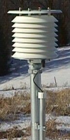
While the mesh hull already somewhat protects the sensor, for reliable and more precise readings it is probably best to isolate it from direct sunlight and rain (snow etc.).
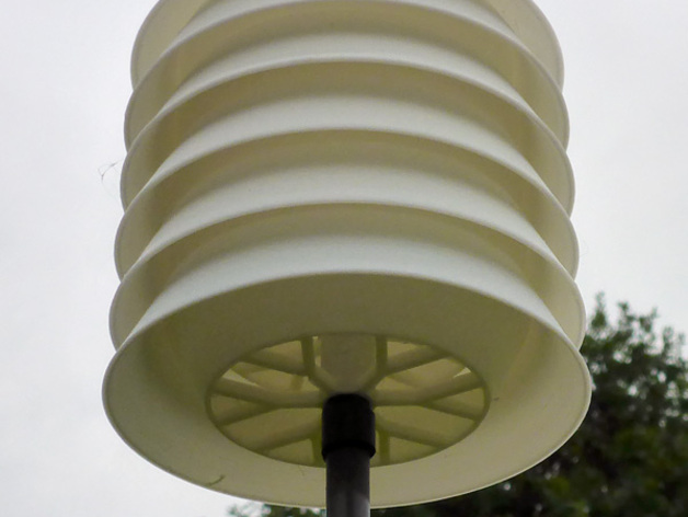
In your current setup the metal mesh hull is on the bottom, unprotected. When it rains it will probably gather much moist because much of the rain caught by the antenna and case will flow over it.
no, its a special enclosure, made for protecting sensors against the elements and also used in commercial outdoor sensors.
for reliable and more precise readings it is probably best to isolate it from direct sunlight and rain (snow etc.).
agree ![]()
How thick is this material?
While used in commercial outdoor sensors, putting it on the bottom where most captured rain water will flow to is probably not the best location for it.
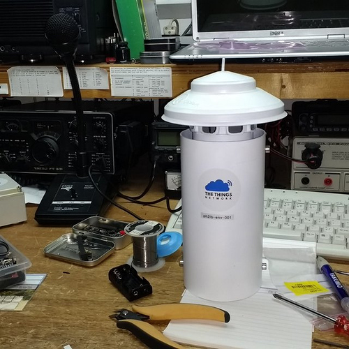
next version maybe… this is a battery endurance test

Something like this would be nice (but in small form factor like on small weather stations).
Maybe a nice project for a 3D printing enthusiast.
lex_ph2lb also found a nice solution
but you can 3D print it yourself
but in my experience with 3d printed display bezels … it will look very bad after a year
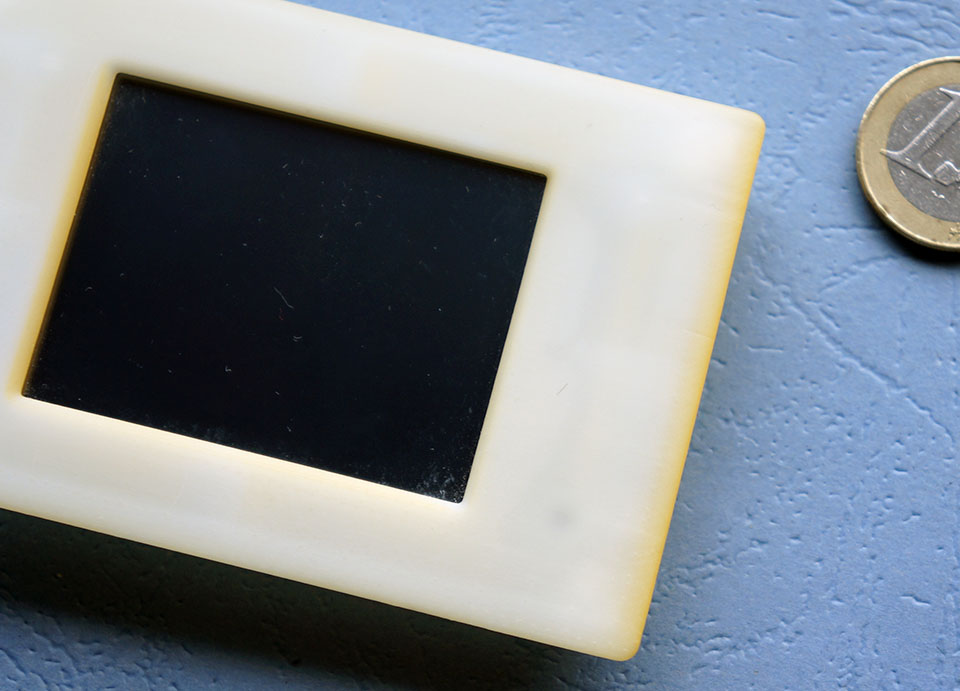
this bezel was made by ITEAD, I bought it together with a small nextion display.
and look what happend to the material … it was bright white when it arrived here.
2 Likes
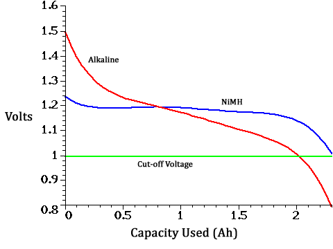
testnode running 1 week … AA battery dropped from 1.56 to 1.52 with an update every 5 minutes

this node should work with a battery voltage down to 1 v
1 Like
You are using Alkaline batteries I assume? 0.04V drop in a week at updates every 5 minutes isn’t that bad for a fresh battery because that tends to drops fast at the beginning, but it isn’t very good either.
At what SF is the node sending? are you using ADR with OTAA?.
As you are running it near your gateway SF7 should suffice, if it is running at SF12 then energy consumption for the sending part will be roughly 32 times higher (if I did the math correctly). Ah think the SF is SF7 looking at a previous post in The WORKBENCH part 1 - #55 by BoRRoZ. Did you measure the standby consumption already?
But I’m not telling you anything new I guess ![]()
Maybe this thingy deserves its own review/discussion topic?
Yes its running on a fresh AA duracell battery
OTAA and I haven’t seen any ADR activity (I can reach 2 or 3 GW on SF7)
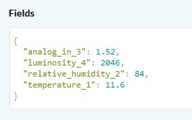
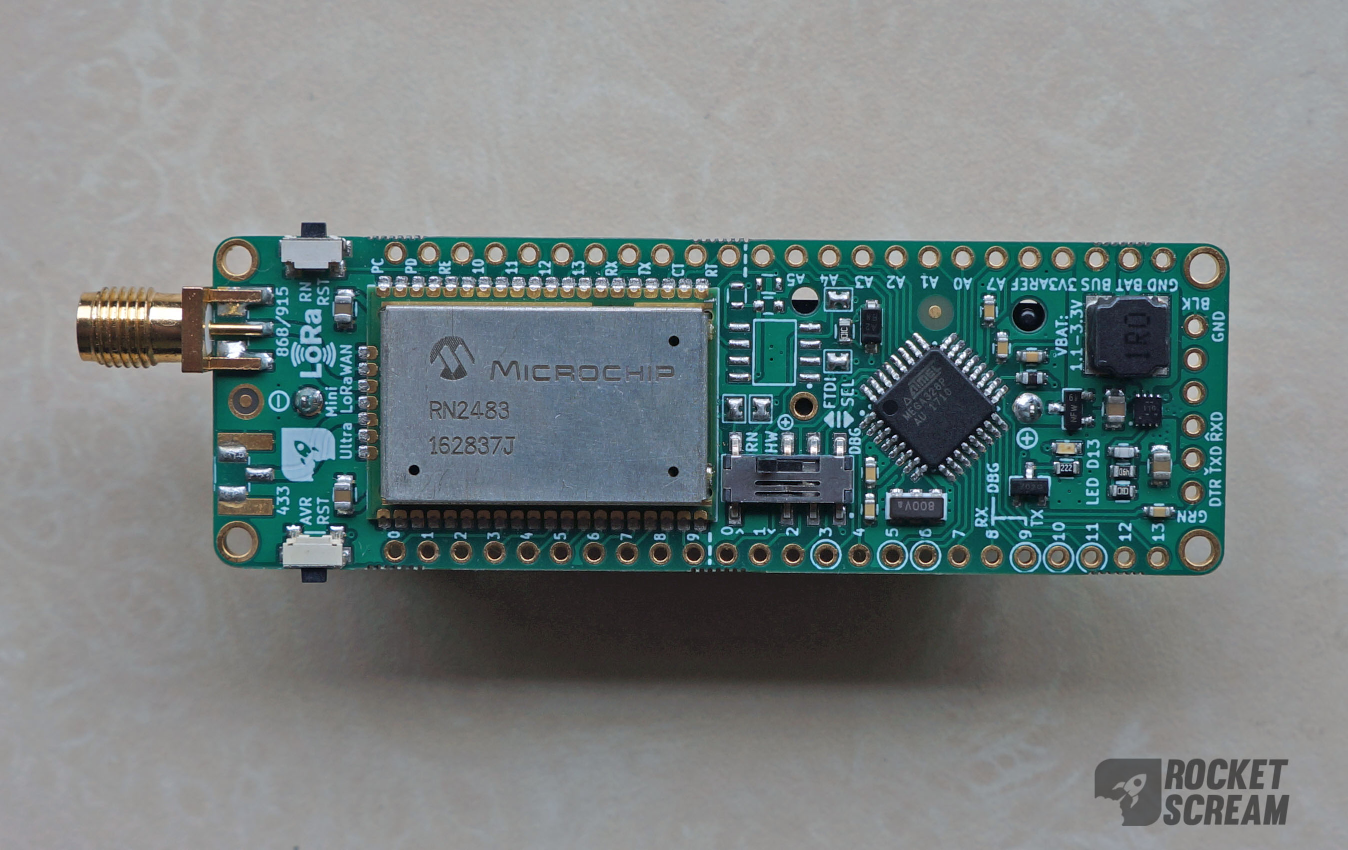
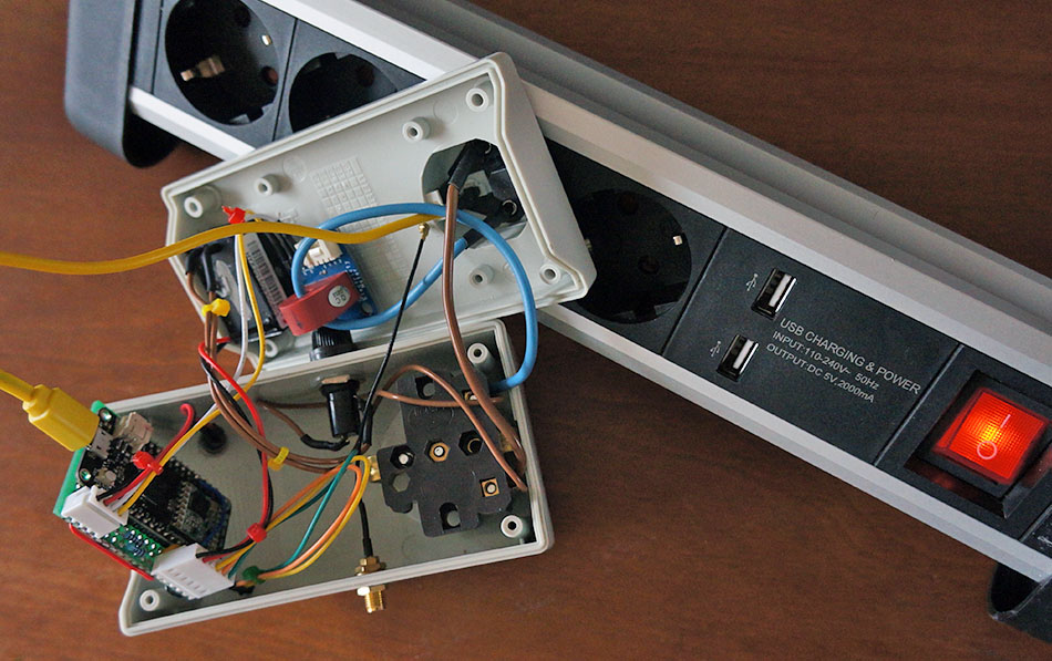
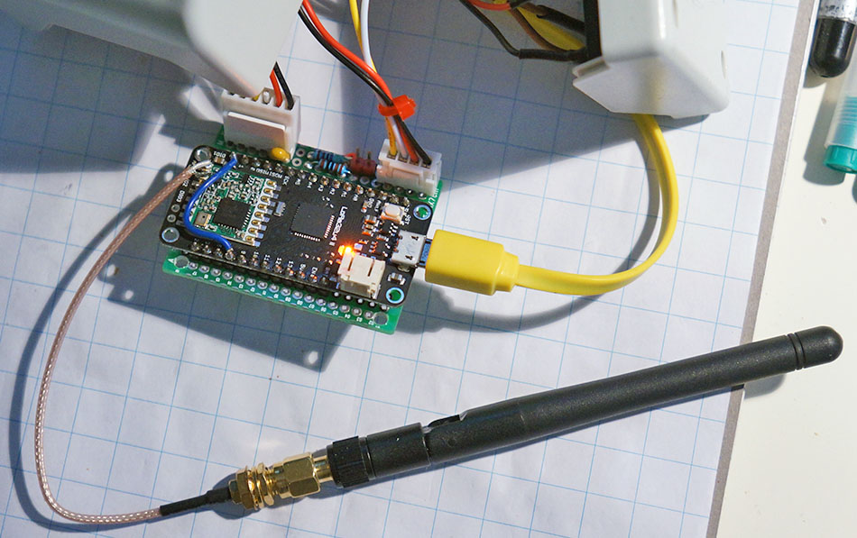
basically Its a 328P+ BME280 with a RN2483, and this one is responsible for waking up the 328p.
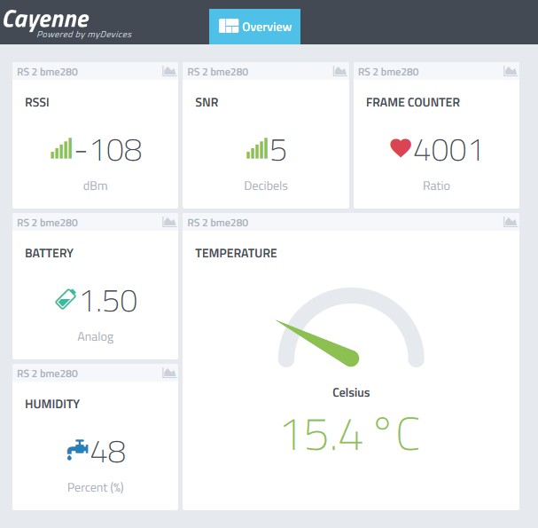
sleep = 50 uA and Tx = 20 mA @ SF7BW125 and test payload = CayenneLPP 28 bytes
planning is / was to let it run until it dies… but we have had a little problem, started this afternoon with Cayenne updates, luckely Cayenne (and TTN) support is very active and looking into it @ this moment.
problem fixed 
2 Likes
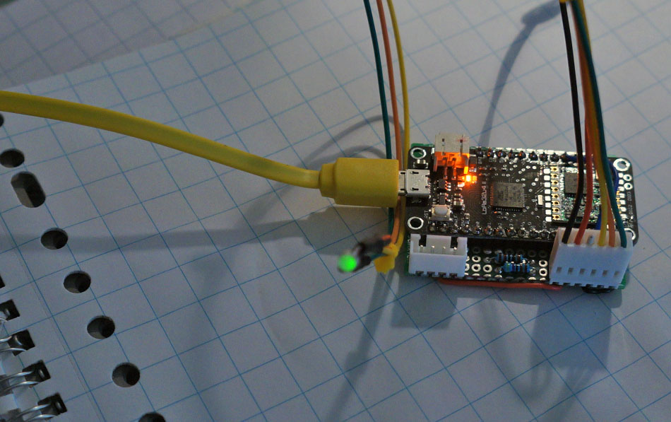
hardware done… now some code, first the dual colour led blinking sequences
- connecting
- can’t find network
- connected / standby
- power on
- heartbeat
no smoke ? 
1 Like
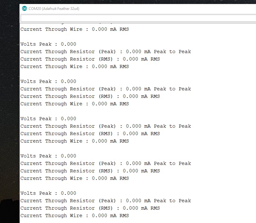
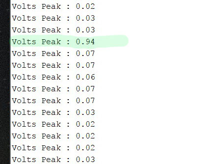

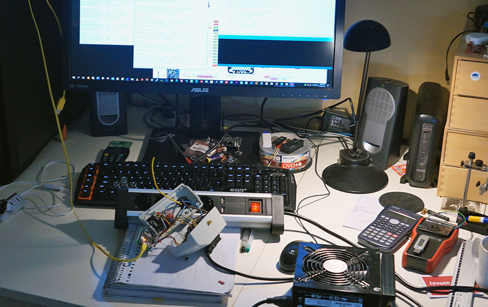
detecting AC current is very easy, as an ‘AC testload’ I use a PC powersupply
so now how do I make a bi colour led blinking a pattern without disturbing lmic…
You run your LED code in a separate function on the other ESP32 processor core as explained by Andreas Spiess - Video link posted on the BIG ESP32 thread
tnx… one little problem, I use a 32U4 
I have allready looked here … blink without delay
guess I’ll have to try that with lmic running
Eh, my bad. sorry! I thought I had seen an ESP32 inside the enclosure on this thread. In any case I am curious to see how you get on as I have 4 of these due any day from eBay.
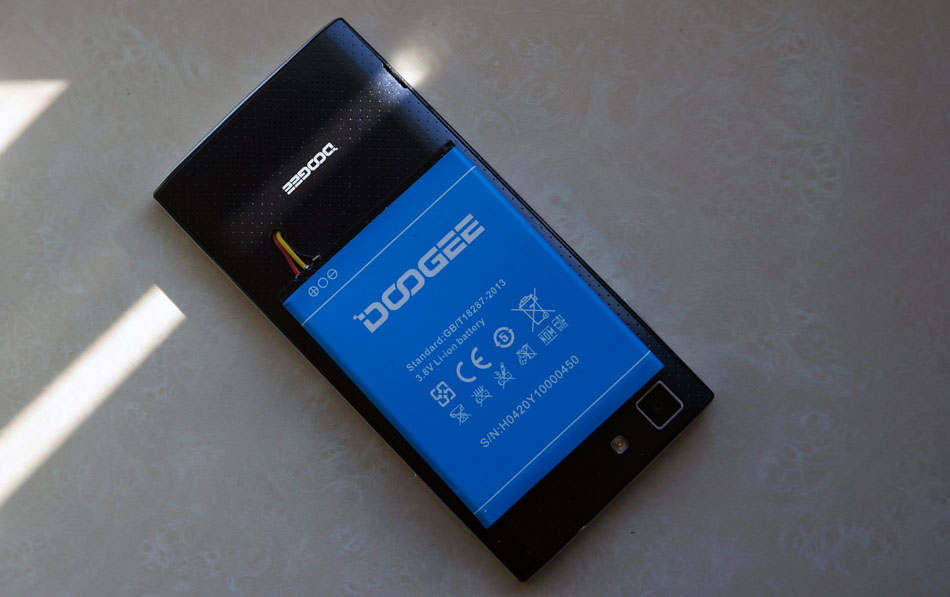
’ you want this smartphone, I can’t buy a battery for it any more ’
sure… now I have a dedicated TTN mapper 
going into week 3 with a single AA battery
* inside is the old hw version of the RN2483 (with firmware 1.03) so curious to see what happends when it starts freezing… we’re close to that point at night.
So as I am not a programmer I may be offering an other humble apology here but a question;
Can you #include <Ticker.h> and call a function to decide which LED on your led flash interval and then
bool ledState = !ledState;
digitalWrite(green, ledState);
What for the beginner like myself will be a problem with LMiC? Is it very sensitive to being blocked?
Thx, G
tnx for the idea
its just me who wants a fancy not neccessary blinking multicolour led interface …
if I just use red / green high/low there is no problem 
* and then only start blinking red when it’s impossible to join the network
problems… sometimes the attached AC load (coffee machine) generates an mcu reset
should I filter the AC before the AC-DC converter or does a node only work reliable on a battery ?
should I ‘shield’ sensitve parts … question questions
- I first must implement a softserial debug port, because now everytime this happends the connection between pc and module is broken because of the 32U4 ‘uart’