But only 27.7 deg C…not quite at the beer threshold per earlier…perhaps it isn’t working so well on the empty battery and you should just reward yourself with a cold one anyhow to celebrate?!  (And settle down to watch the Belgium/England game…)
1 Like
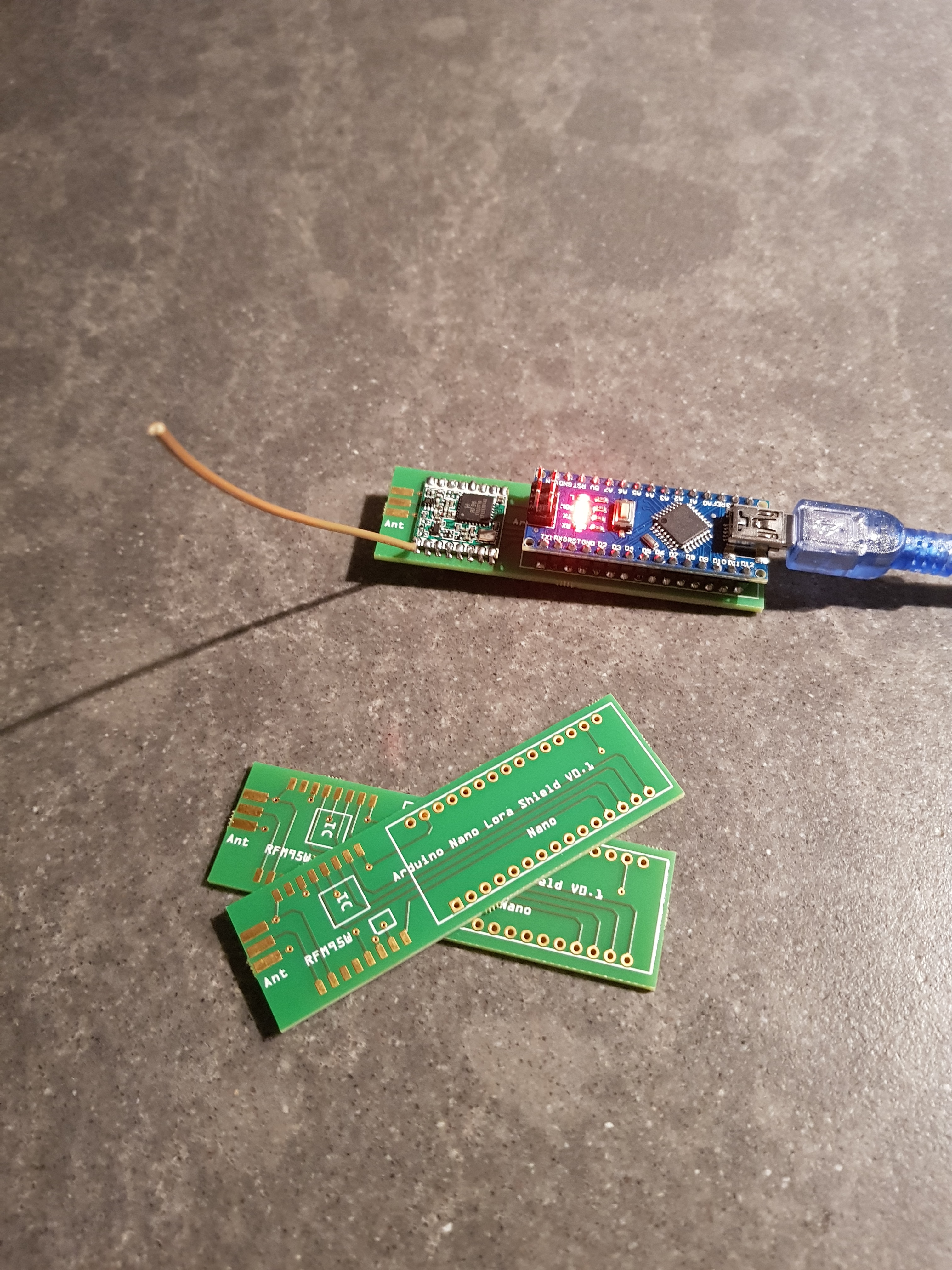
I received today the fritzing design pcbs from aisler. 11 days to fabricate. Put a rfm95 and a arduino nano on it and it works. 
3 Likes
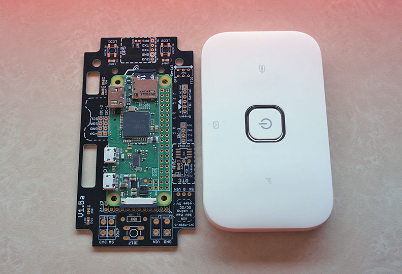
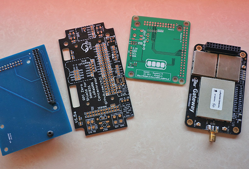
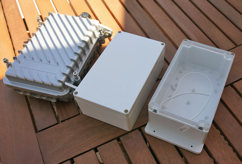
core parts for attempt 1 to build a small portable 3G solar gateway
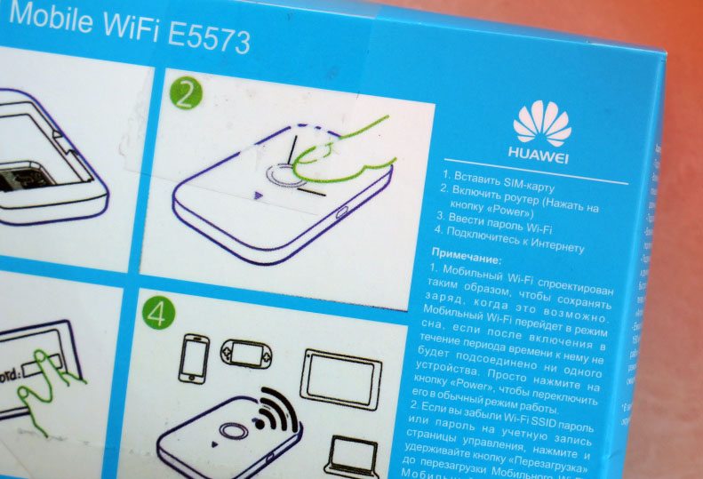
don’t complain when you buy an ‘unlocked’ 3g router 
I’m an adaptercollector 
2 Likes
For a solar powered gateway maybe it would be interesting to get an ESP32 to act as packetforwarder. That could really save some power. What solar cell are you planning?
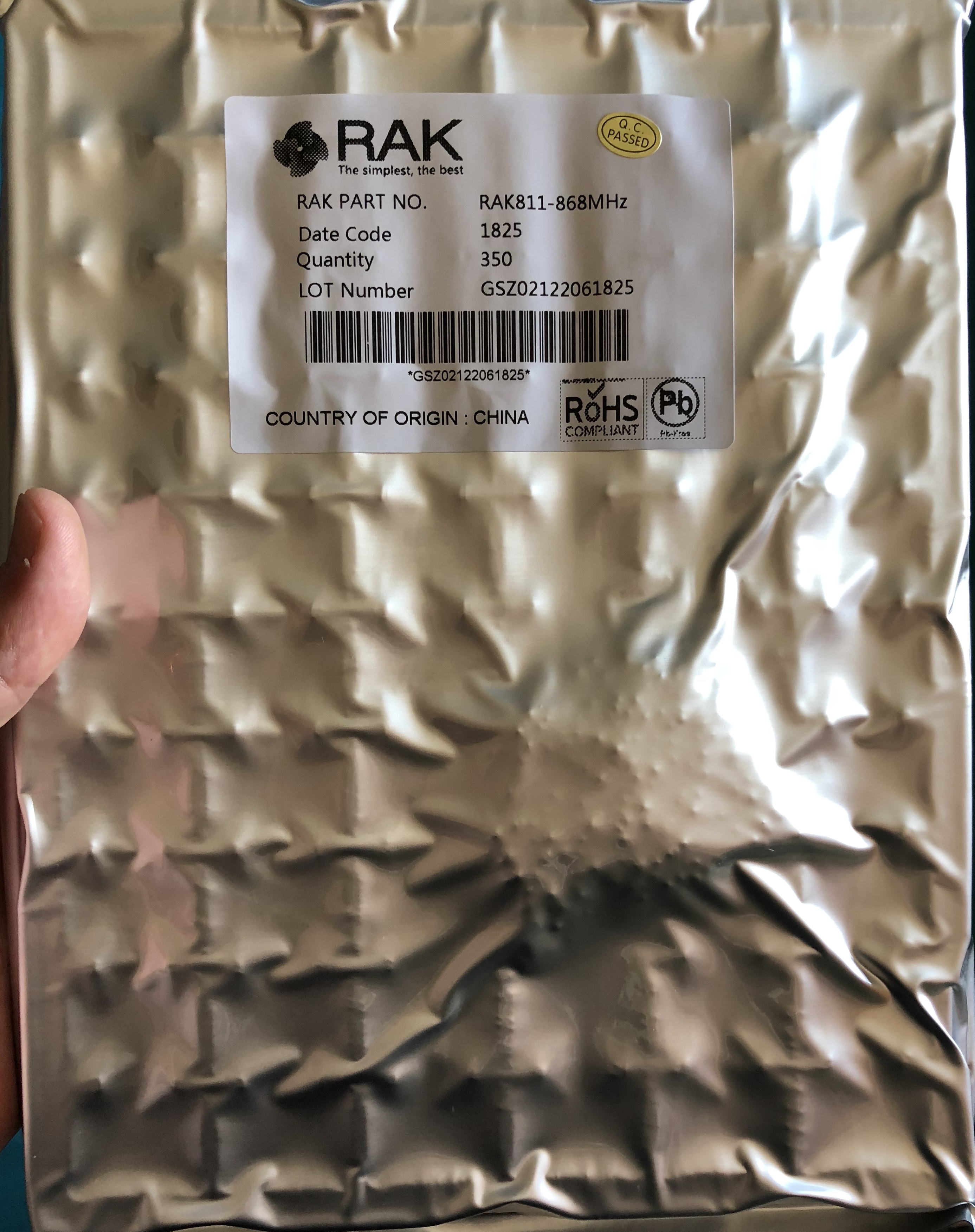
No I’ll stick with the proven PI zero/rak831 combo … the capacity of the powersystem is not known at this moment
1 Like
I see several issues with this PCB:
- Nano is 5V, the LoRa module is 3.3V but no level converters are used.
- The PCB trace from antenna pad to the SMA connector (pads) appears unshielded, so it will act as part of the antenna.
- If you use a wire as antenna as on the photo you should cut the PCB trace to the SMA connector (pads) because in addition to the wire it will act as a second parallel antenna causing impedance mismatch and RF signal loss.

2 Likes
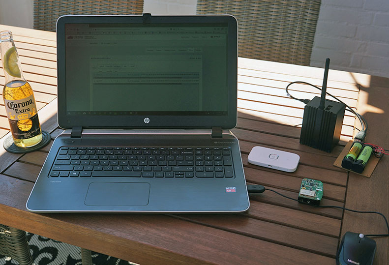
first babysteps … testing mobile 3g gw

1 Like
@bluejedi. Yes your right. I made a mistake. I thought that the nano can run external on 3.3v like a lora32u4 board. Thanks for the tips.
It’s a pity that there never has been a 3. 3V Nano.
A popular alternative is the Pro Mini (needs USB to serial adapter for programming) or Pro Micro (has USB). You will need a 3.3V version (8Mhz).
The Pro Micro’s 3.3V are relatively expensive.
Still having success with the Mexican flux I see!
flux
flʌks
verb
1.
treat (a metal object) with a flux to promote melting.
1 Like
I programmed the nano with a sketch after that i connect the vcc and 3.3v together and connect it to 2 aa batteries. I removed the power led. The nano connect to ttn but it still drains the batteries. Maby ch340 doesnt like 3v on Vcc input pin and 3.3v output.
Connecting Vin and 3.3V together is not good. 3.3V is output from CH340.
The only safe way is to either:
-
On a Chinese Nano with CH340 replace AMS 1117 5V with a 3.3V version and disconnect the schottky diode (is connected from USB +5V to AMS1117 out 5V) from AMS1117 Output and connect it to AMS1117 Input instead.
(And then don’t power from USB and Vin at the same time.) -
Or remove the Schottky diode (you will then not be able to power it from USB anymore) and power it with 3.3V to the 5V pin instead. I have seen AMS 1117 5V that did not care when 3.3V was put on its output pin, but also ones that did not like it and became burning hot (drawing 800mA), so this may not be a good option after all.
According to ATmega328 specs the limit for 3.3V is 12MHz clock max. The 5V nano uses a 16MHz crystal or ceramic resonator. Running ATmega328 at 3.3V with 16MHz clock can work but it runs outside the specs (I have some but have not tested them to their limits).
To stay within specs you would also have to change the crystal/resonator to 8MHz (or 12MHz), but then you will probably need a custom bootloader and/or a custom board definition as well.
So, a lot of fuss. Using a standard Pro Mini or Pro Micro is much easier.
And you need to separately power the LoRa module with 3.3V anyway (you cannot use 3.3V out from the Nano for that).
1 Like
Anyone want to see pick and place photos?
3 Likes
Of course we all love to see some electronics porn
3 Likes
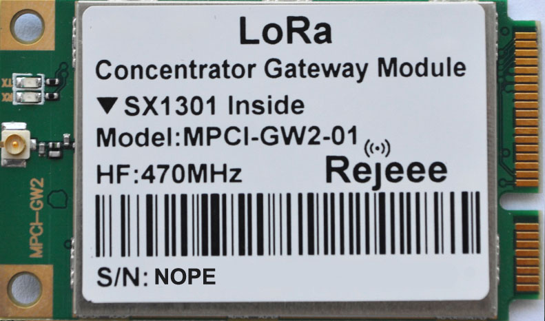
Wrong frequency…
Maybe @BoRRoZ moved to China already
Nope, his application would be Rejeeected…
Ok, I am out
