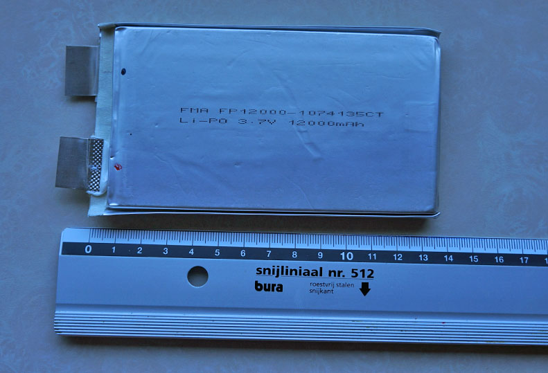
first 1 (of 4) 12000 mA LiPo for diy mobile powerbank
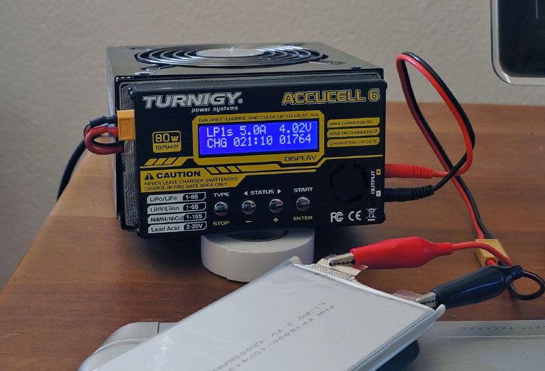
carefully pump it up 
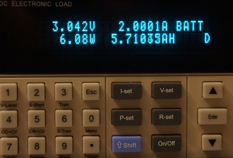
testing ‘real’ capacity vs advertised one 
first 1 (of 4) 12000 mA LiPo for diy mobile powerbank
carefully pump it up
testing ‘real’ capacity vs advertised one
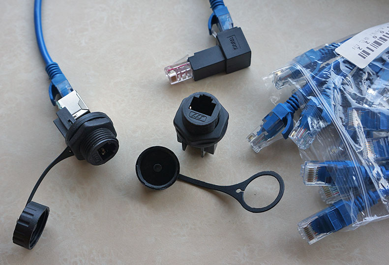
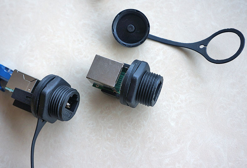
material for waterproof mobile outdoor GW build arriving
YES ! it’s officially released… 


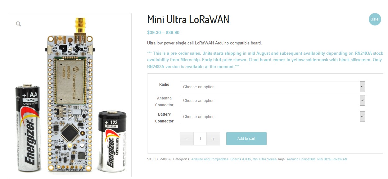
about the design of the board : http://www.rocketscream.com/blog/2018/06/18/single-cell-arduino-compatible-lorawan-low-power-node/
hmmm… that could fit with a bit of hacking off course
Received a new pcb from aisler. 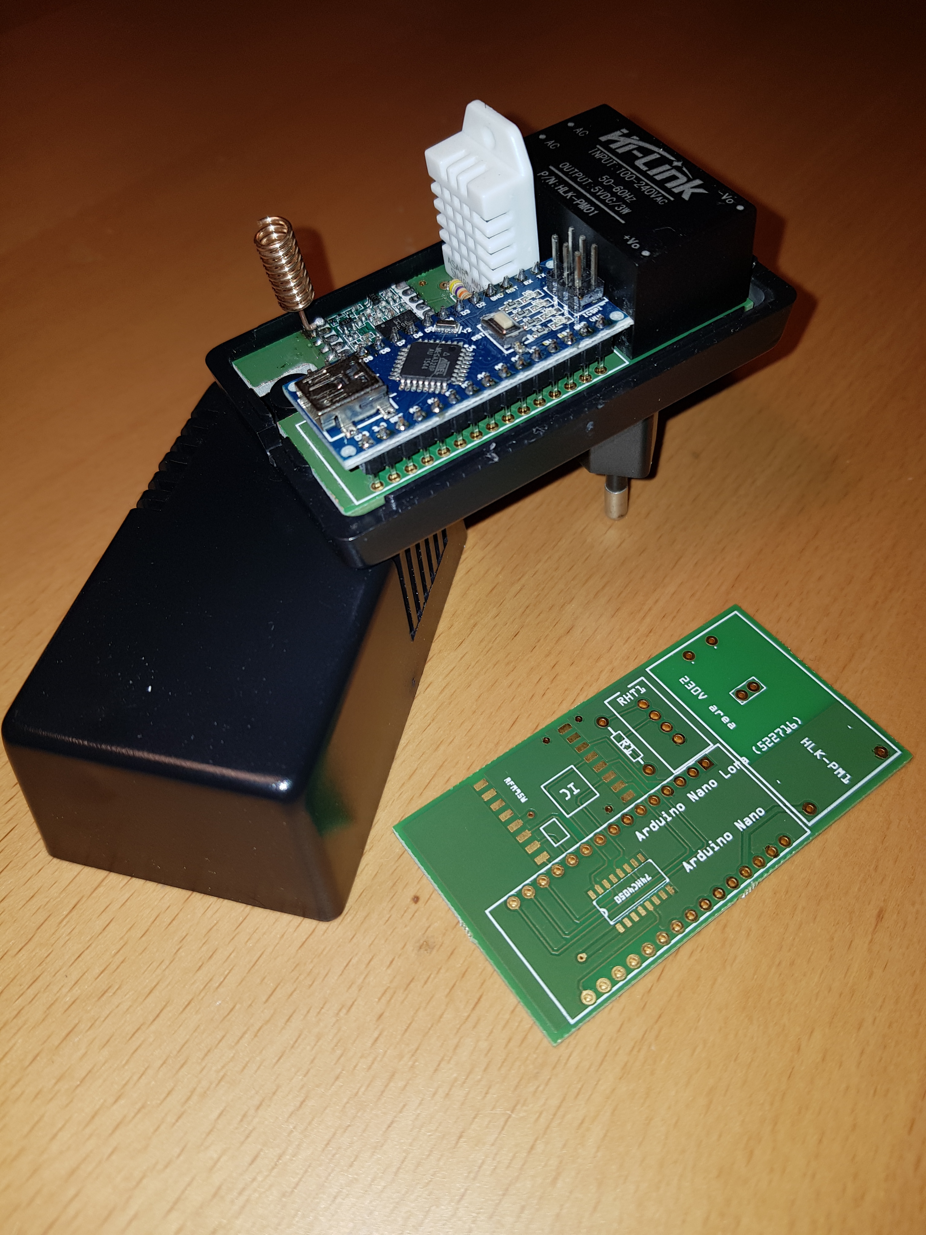
nice… AC powersupply with a hi-link, just plugin somewhere and you can measure the room 
have a link for the enclosure ?
found one here
what’s missing is build in safety , like a fuse and a varistor
Personally, I find if you tip the bottle to slightly pursed lips it fits just fine, with good water tight seal - no need to hack bits of the bottle neck off to make it work! 
(Though the optional lime can sometimes create obstruction…  )
)
@BoRRoZ. Yes case is from conrad, number is on the pcb. 522716. The two lines to AC mains are close together. The next version i shall correct this. To fix it now i wil use my dremmel 
Hey @BoRRoZ
Use an used TP-Link 841 V9 and Freifunk or Freemesh to do that.
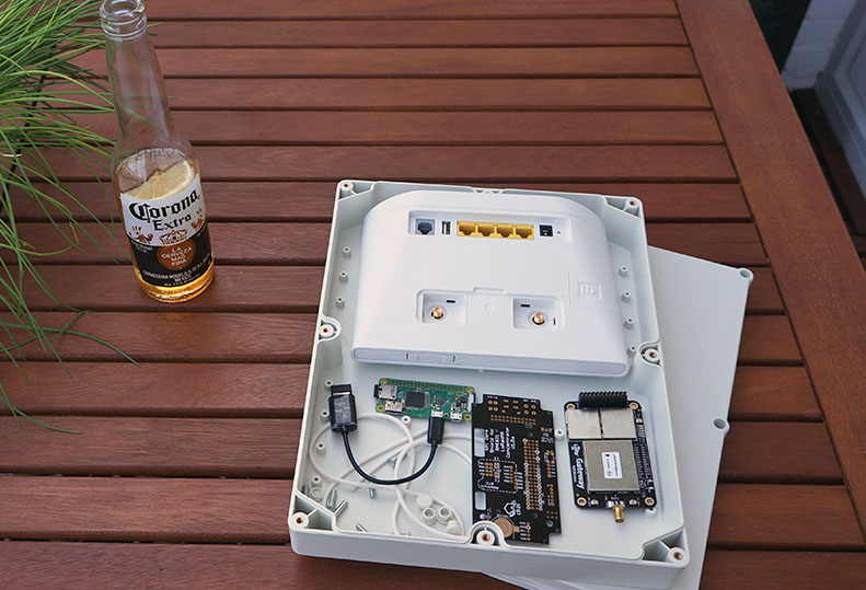
When i see that, i see the same problems like me. Sandwich ( Pi&Backplane&Gateway) are to high.
Needing an PCB we can stick the Pi and GW side by side and an little bit “magic” on it (hum, temp, power, I²C, con`s).
Greet`s
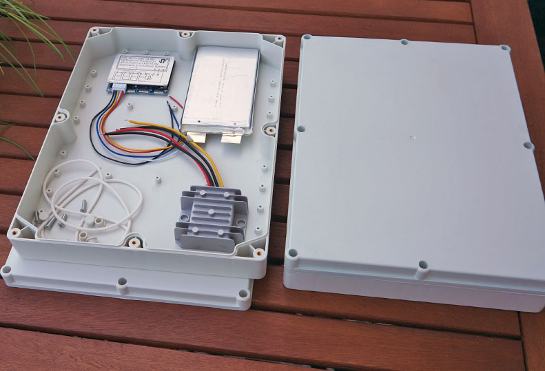
wait till this mobile 4g GW is finished  … I had some trouble with the power but that seems solved.
it gets a heavy 5v/12v 17000 mA system build in so it can run for days
and yes I have a very low enclosure (must fit in backpack ) So probably I don’t use an adapterboard but wire it myself.
Ahhhhhhhh mobile! Understand.
my reason is stationary. But share not only IoT (TTN) GW. I share my DSL (Internet) for free.
Freifunk is not free beer! We share the way for people they need information! We dont filter, we dont track! We are free! Get the digital cup of water, that stand at my site. I don`t ask where you are, what you are or where you from!
uhhhhhhhhh… It is a little bit off topic. We made our own network!
Have a nice day
and this was our commercial break… back to the studio ![]()
Sorry. but were are NOT!!! commercial!!! :-p
only joking… I know
you have some links about Freifunk … be my guest and place them here 

made a little mistake yesterday and my labpowersupply is dead now 
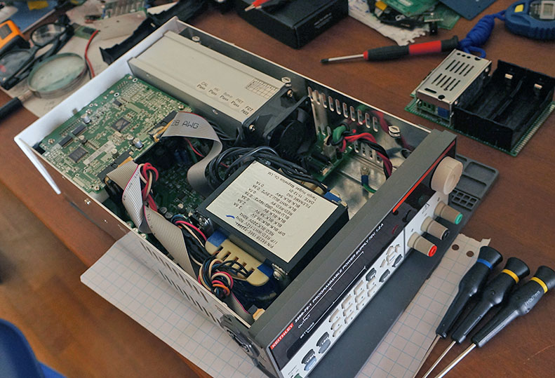
problem : can’t find schematic of this keithley 2200-72-1
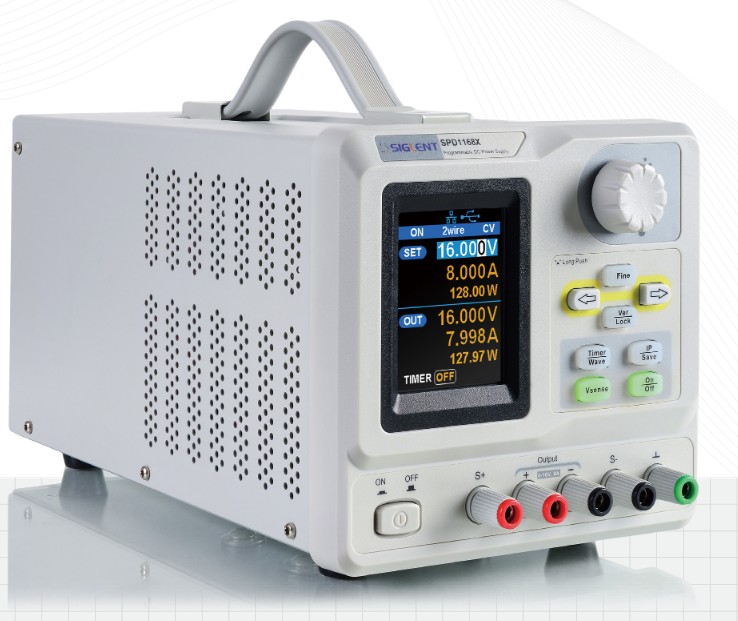
this new siglent type looks like a nice replacement ( I don’t need 30-35 volts but I need/like 8 amps)
Why not ask for the schematic, or help on the EEVBlog-forum…
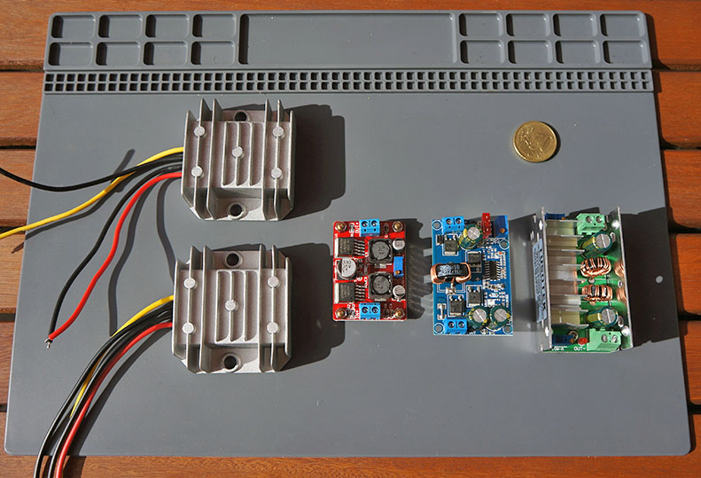
buck / boost / buck-boost DCDC converters for higher currents (>2A)
cool … it works !
that’s good advise
I previously did some measurements of OLED display power consumption in:
Big ESP32 + SX127x topic part 2
I removed the voltage regulators from four of the OLED displays (B, D, E and I, note that display numbering is not identical to my previous test) to see how much power consumption would drop when the display is switched off (from software) and the power consumption with display off dropped substantially (see column VReg removed). This difference is caused by the quiescent current of the regulator.
For some displays where the regulator is removed the power consumption when the display is on increases a little bit. This can be explained by the following: when the OLED board is provided with 3.3V supply voltage the display will get slightly less due to the regulator’s dropout voltage. When the regulator is removed there is no dropout so the display will get a slightly higher (3.3V) supply voltage.
All displays are blue, use I2C interface and use pin order GND, VCC, SCL, SDA. All
displays came with a XC6202 3.3V voltage regulator (code 662K) for 5V/3.3V operation.
From four displays the regulator was removed to minimize current usage when display
is off to make suitable for (3.3V based) low-power applications.

Disp off is display off/powersave/sleep.
Disp off VReg removed is after the 3.3V voltage regulator was removed from the PCB.
% pixels: display on and % pixels is the percentage of pixels that are lit.

Display Type            Disp off    Disp off      0% pixels 50% pixels  100% pixels
                                    VReg removed

A       0.96" 128x64    13.7uA                    1.4mA      8.7mA      11.4mA

B       0.96" 128x64    12.8uA                    1.5mA      9.6mA      13.2mA
                                    3.2uA         1.5mA      9.7mA      13.3mA

C       0.96" 128x64     7.7uA                    1.6mA     14.7mA      24.3mA

D       0.96" 128x64    32.5uA                    1.5mA      9.9mA      14.1mA
                                    4.1uA         1.5mA      9.9mA      14.2mA

E       0.96" 128x64     7.0uA                    1.5mA     16.4mA      29.4mA
                                    1.2uA         1.5mA     16.7mA      30.2mA

F       0.96" 128x64     8.4uA                    1.5mA     16.1mA      27.9mA

G       0.96" 128x64     7.0uA                    1.5mA      9.9mA      13.2mA


H       1.3" 128x64      7.4uA                    2.2mA     22.4mA      30.1mA


I       0.91" 128x32     8.3uA                    2.2mA     16.7mA      21.8mA
                                    1.2uA         2.2mA     16.7mA      21.8mA

J       0.91" 128x32     8.1uA                    2.0mA     18.7mA      33.1mA