Where did you get the lora node housing from ?
Enclosure from Spelsberg TG PC 1212-6-o
1 Like
With “AVR quirks” are refering to the AVR 8-bit (ATmega) stuff or to SAMD? If SAMD, what quirks and oddities are you referring to?
AVR quircks. Like if you declare a GPIO as input that you can write to it to enable the pullup. This type of bizarre thing.
Do you mean that in order to be able to select a different upload speed, when using your bootloader it is not required to use your boards definition but for the MiniCore bootloader it is required to use your boards definition?
(And of course this will be limited to the boards defined in your boards definition.)
IIRC upload speeds are defined in the boards definition, not in the bootloader(?), because in that case your boards definition would be required for your bootloader as well (if one wants to change upload speed).
What is the upload speed used if it cannot be changed in the IDE (i.e. when not using your boards definition) and would that fixed upload speed cause any problem (other than that it is slower)?
@bluejedi
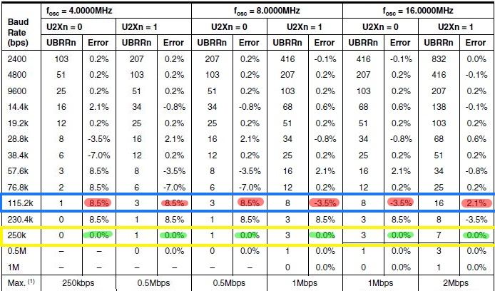
my bootloader is almost the same than mini core (may be blinking led twice at startup on mine) but core is the same. If you flash bootloader to run at 250KBPS (mine or mini core) you won’t be able to upload with mini core Arduino IDE definition because you can’t change speed of upload (in this case 250KBPS)
On upload view, the only difference on my boards definition and mini core is that mine allow to select upload speed so if you change the default one which are for mini-core 16MHz 115200 and for 8MHz 38400.
Anyway, you can upload with my boards to mini core and vice versa but if you use different speed than the 2 above you need my board definition (or change the one of mini core)
My 2 cents, avoid any issue, if you flash bootloader flash the 250K version, upload is a must and works even at 4Mhz
2 Likes
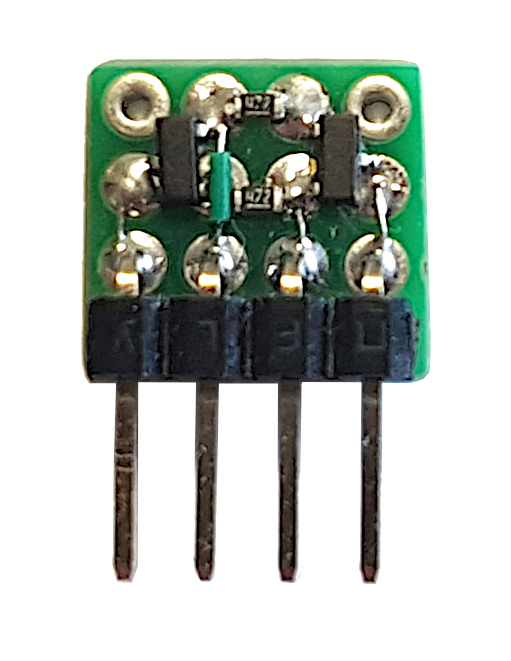
Yes, I’m using these too. They are very flexible and also useful for ‘bare’ (boards without USB and regulator) ESP32 and ESP8266 development due to it’s separate on-board 3.3V voltage regulator.
In addition to most common USB to serial adapter you can select this adapter to wire either CTS or RTS for auto upload/auto reset use. For normal use (AVR and alike) CTS should be selected (most are default jumpered for RTS!).
Setting it to RTS is useful for ESP32 and ESP8266 because these normally use RTS instead of CTS. But is only of interest for ‘bare’ ESP32 and ESP8266 (without USB) when you add the hardware for it (2 transistors + 2 resistors) yourself.
Note: the voltage jumper has to be set to either 3.3V or 5V. Without the jumper it will not work. If you want no VCC on the VCC output pin you will have to cut the PCB trace to that pin, but still need to select a voltage with the jumper.
Unfortunately they are not reverse power supply voltage protected. ![]()
Nice, good to know ![]()
I was able to use the Wemos CG340G USB to serial with below boards to enable auto program/reset over USB because it can be configured to use RTS instead of CTS.
Bare ESP32 prototyping board:

With hacked ESP-WROOM-32 (rev 0) module to make two extra pins available:
SENSOR_CAPP (pin 6): GPIO37, ADC1_CH1, RTC_GPIO1
SENSOR_CAPN (pin 7): GPIO38, ADC1_CH2, RTC_GPIO2
ESP auto program/reset logic (for breadboard prototyping):
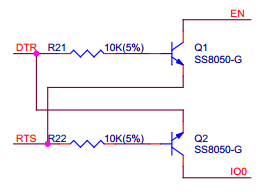
(Pins: IO0, DTR, RTS, EN)
1 Like
Damn…
Magic smoke at Kiwi Electronics 
https://tweakers.net/nieuws/155214/raspberry-pi-leverancier-kiwi-electronics-is-getroffen-door-brand.html
 yep… nice dutch webshop
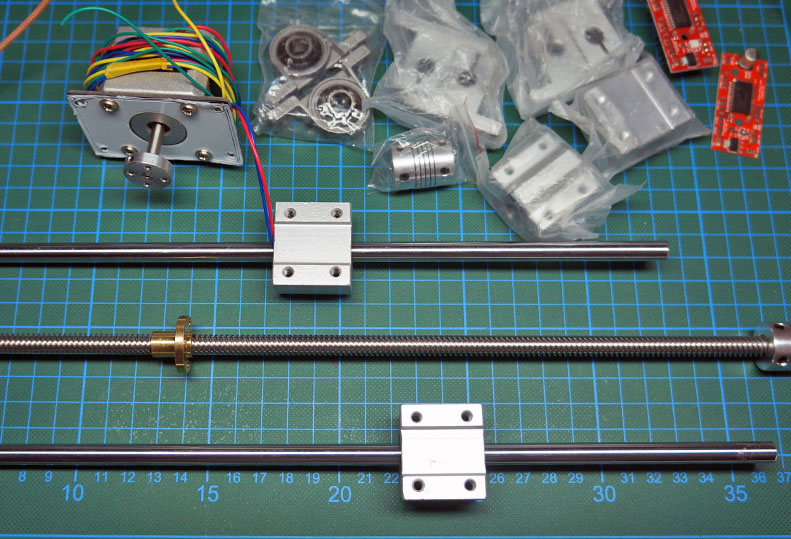
no, it’s not a 3D printer under construction 
That probably leaves engraving, (laser) cutting or CNC
(assuming that you are not going to build your own scanner or matrix printer  ).
).
nope… it will end up as x-y table with joystick control for my microscope …
Nice!
while searching for the missing parts in Uncle Ali’s shop, I found these 30 RPM 6v motor/gear assembly
bought them … the plan is to use them to auto adjust the angle of the 4 small solar panels I bought before.
Imagine a plastic tube with this inside and on the outside the solar panels, hinged on the top
when you start the motor all 4 will elevate… well… that’s the idea 

Hi guys,
I’d like to share the PCB design for a LoRa MCU board powered by an ESP32-WROVER-B with the RFM95W module. The design has an onboard 868MHz antenna with 5dBi gain. Tested and works perfectly with TTN.
The board is designed with a 24Pin Header to allow sensor modules designed specifically for this board to be plugged on as daughter-boards. So you can design your on sensor board and attach to this. Daughter boards can either take power from the 3.3V pins or provide power from the 5V pins.
Firmware can be Arduino, Micropython or mongoose OS.
The full CAD project is online here
Full details are available on the GitHub page
7 Likes
wow… that’s a great project ! thank you ![]()
I have also used the DN024 design it is very good, your antenna seems to be cut for 915MHz though.