The WORKBENCH part 5

Looks like the BBC microbit getting update…


uBit + @rakwireless @rakwireless2020 ‘811 add-on bd from @PiSupply running an edge AI routine for smart sensor anyone?

Fleshing out a bit (excuse the pun!) more tech detail:

2 Likes

Found this little ATmega328P + RFM95W combo on AliExpress …

ATmega328 board

RFM95W

Small box of 5, separate MCU board + radio chips cost £22.27 aka £5.44 each. The vendor sells a number of combinations for regional frequencies or using RFM69.

The PCB doesn’t have a link for DIO1 trace, hence the yellow wire. Took about 5 minutes to solder and three minutes to setup ABP & download using Classic LMIC and see uplinks.

Tomorrow I’m make another, add DHT11’s & a 7805 Vreg and wire them to both cars that are suffering badly from damp at present - may as well get some hard data on the problem.

To students and beginners, these modules are very entry level, the principal problem is the shortage of memory - they are cheap, good for ‘disposable’ devices or only requiring one or two simple sensors. They are not a good match for those wishing to warp time & space by rushing to an end result.

5 Likes

Hi Jeff

Did you run the tests on the LDDS75 Ultrasonic Distance Sensors?

1 Like

They seem to be a copy of the Moteino boards: https://lowpowerlab.com/guide/moteino/

1 Like

So they do, normal mode for Chinese entrepreneurs :roll_eyes:

1 Like

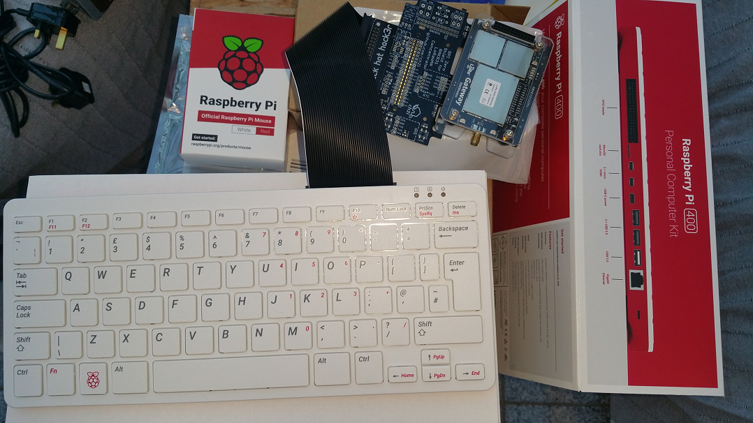
With the launch of the new Raspberry Pi 400 Keyboard kit ( The LIBRARY basement part 12 ) I was scratching head thinking how to best use my new acquisitions.

Then it struck me - add 40way external cable, break out connector bd &/or interposer board such as one of those from Charles/Ch2i used previously with RPi0W’s, drop in a SX13xx concentrator card such as those from @kenyu and our friends at @rak such as this one contributed by friend of the TTN @jmarcelino and Bingo! :tada:

An integrated GW development kit :slight_smile: :rofl: - just need to break out the soldering iron and smd reflow kit :wink:

image

image

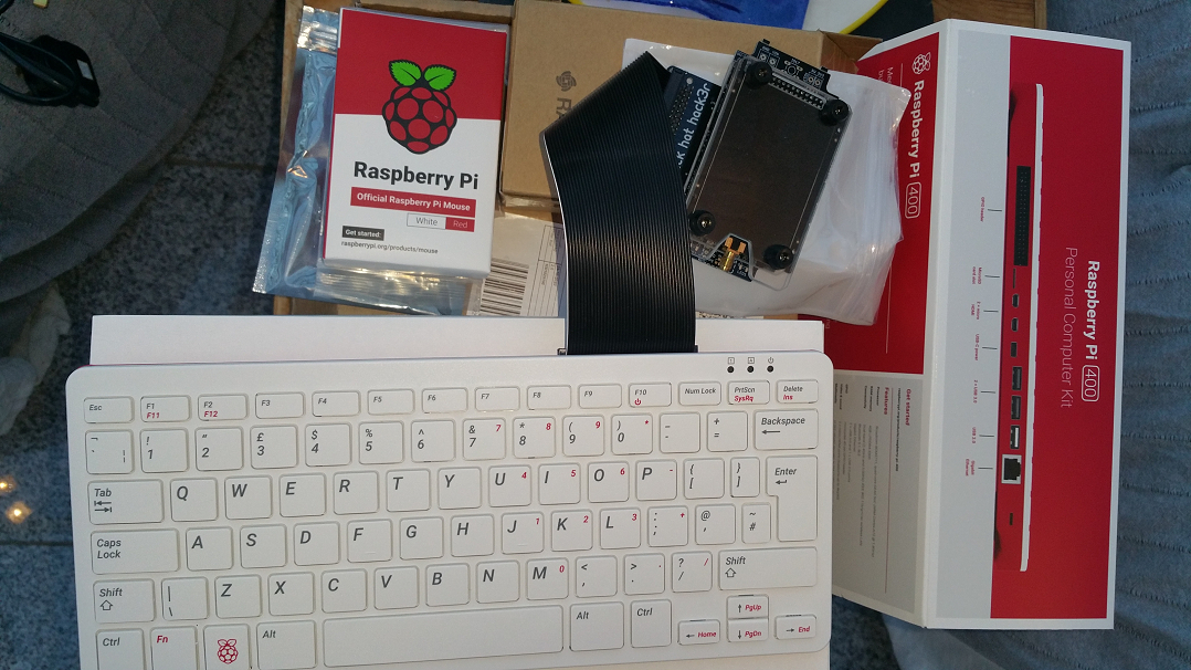
Guess what me and the kids will be playing with over Xmas & New Year?!

4 Likes

A smoldering pile of chips & plastic?

1 Like

It’s been a while since I had inspiration and time, but this week Aliexpress has been good to me.
PXL_20201113_102426792

2 Likes

A post was split to a new topic: Problem registering Dragino ldds75

Here is something that should be on your workbench: https://nl.aliexpress.com/item/32876049554.html?spm=a2g0s.12269583.0.0.4d4425a6RHIncR

afbeelding

2 Likes

Seeed seems about to release a new LoRaWAN module:

LoRa-E5 STM32WLE5JC Module, embedded SX126X and MCU for LoRaWAN Wireless Sensor Network & IoT devices - EU868 & US915

2 Likes

I just had one. Ordered on the 11th, arrived in the UK on the 16th.

The useful mod I saw on You Tube is to add a switch to turn off just the heater elements, so you can still keep an eye on the plate temperature.

I can bin my electric frying pan at last.

2 Likes

I have had a chance to try the hotplate.

I have been working on a ESP32 based PCB that can take a choice of SX126X, SX127X or SX128X LoRa modules. I have versions of the board for Pro Minis, but that does mean they lack in program space.

I first used the hotplate to remove an ESP32 from a previous PCB. Once I had worked out the right temperature setting to use it was very easy to heat the old board and remove the ESP32. If I had heated the board from above with a blower, there would have been the risk of maybe unsoldering all the bits inside the ESP32.

I soldered the ESP32 in place by hand on the new board but when powered up there was a fault. Eventually it seemed to be a short between the ESP32s GND and VCC pads. So I used the hotplate to lift the ESP32 and found and corrected the solder bridge. I placed the ESP32 over the pads again, let the hotplate heatup and the ESP32 neatly soldered itself back in place. No heat damage to the PCB at all. Overall a very easy operation.

The temperature indicated was maybe 25C out from what the setting was, so perhaps you might not want to use this hot plate for making commercial stuff, but for the DIYer it is well worth the money.

The board by the way has a power supply that survives the WiFi switch on current pulse and has a deep sleep current of 20uA. There is a FRAM and a micro SD card holder on the back. Even the LoRa modules work.

Easy_ESP32_Complete

Easy_ESP32_Detail

2 Likes

Connecting LoRa devices to 5V Arduinos.

I am sure that observant LoRaites will have noticed that for the SX127X LoRa devices the data sheets have no maximum voltages stated for the logic pins, SCK, MOSI, NSS etc. This is very odd from Semtech, are users of the devices supposed to guess ? So what does the lack of information mean, that the pins are 5V tolerant possibly or that it does not matter and you could put many kilovolts on a pin with no risk to the device ?

We all may assume these LoRa devices are 3.3V logic devices but some who try it say they do work (for a while at least) when hooked up to a 5V Arduino such as a UNO.

So I checked what happens when I connected a SX1276 LoRa module to an Arduino UNO (do this at your own risk). The device appears to work, you can read and write to registers etc. However the LoRa device is putting out signals of around 4.2V peak on the MISO pin.

This is odd I thought, the device is only connected to a 3.3V supply ?

Turns out the LoRa device is being phantom powered by the 5V outputs of the UNO, NSS and MOSI and this raises the LoRa devices VCC supply to around 4.1V.

Oh dear … the absolute max voltage on the VCC supply pin is 3.9V and the operating range is listed as 3.7V max.

So thats why you should not connect 3.3V LoRa devices directly to 5V Arduinos.

5 Likes

A potential client interested in deploying one of these:
image

powered by one of these:
image

Wanted an easy way to monitor the battery voltage. Problem was I didnt have a lot of free time to build a low cost node lash up and I also decided it would be useful to report the solar panel output voltage. Then I remembered I has a Dragino LT-33222 from our friend @edwin and the team. Perfect - supports 2 analogue input voltages for monitoring (0-30V) as well as running off a supply upto 24V, thereby allowing a direct connection to relevant circuit points without any adaptation or changes. A bit more expensive than a self build perhaps but time is money and a better value proposition at the time. Also ( :thinking: ) it has a number of Digital I/O and relay contacts so next step is to consider how these might be used for battery & load switching/failover automation, etc…

Lash up circuit with output taken directly from TTN Integration to Cayenne dashboard (for easy sharing with the client)
image

Installed and happily running for a couple of weeks now as part of the system POC
image

8 Likes

For anyone itching to play with one since last weeks TTConf:

1 Like

Prototyping - now I know what the longer breadboards are for …

Big-mess-o-wires

1 Like

Raspberry Pi Pico, DS18B20 on 1-Wire library from the original code so not production ready, RAK4260 module.

Pico_DS18B20_LoRaWAN

The Pico in the foreground is a Pico setup as a programmer / debugger.

Still working on the exact figures but the Pico isn’t going to be suitable as a battery device as the minimum I’ve seen so far is 900uA. As such I won’t be stampeding to use these unless I end up the a compelling use case - probably edge-AI/ML.

2 Likes

Take a couple of RPi Pico boards, a hand full of of LoRaWAN modules (Note not LoRa modules, so you dont have to worry about porting e.g. Aunties version of LMIC or other such LoRaWAN stacks! and avoid wrangling Arduino-like implementations for such), add a few sensors… and a nice weekend project?! If LoRaWAN Stack based devices should go straight to V3? :thinking: what can possibly go wrong?!

image

1 Like

@Jeff-UK, this may help: GitHub - HeadBoffin/Pico-Three-Way-Serial: Serial communications example/starter for the Raspberry Pi Pico board

1 Like