Building the hardware
Note: in the newer sensors I’ve built I went to a design with voltage dividers instead of a level shifter. See the wiring diagram below… the pics still show the old situation.
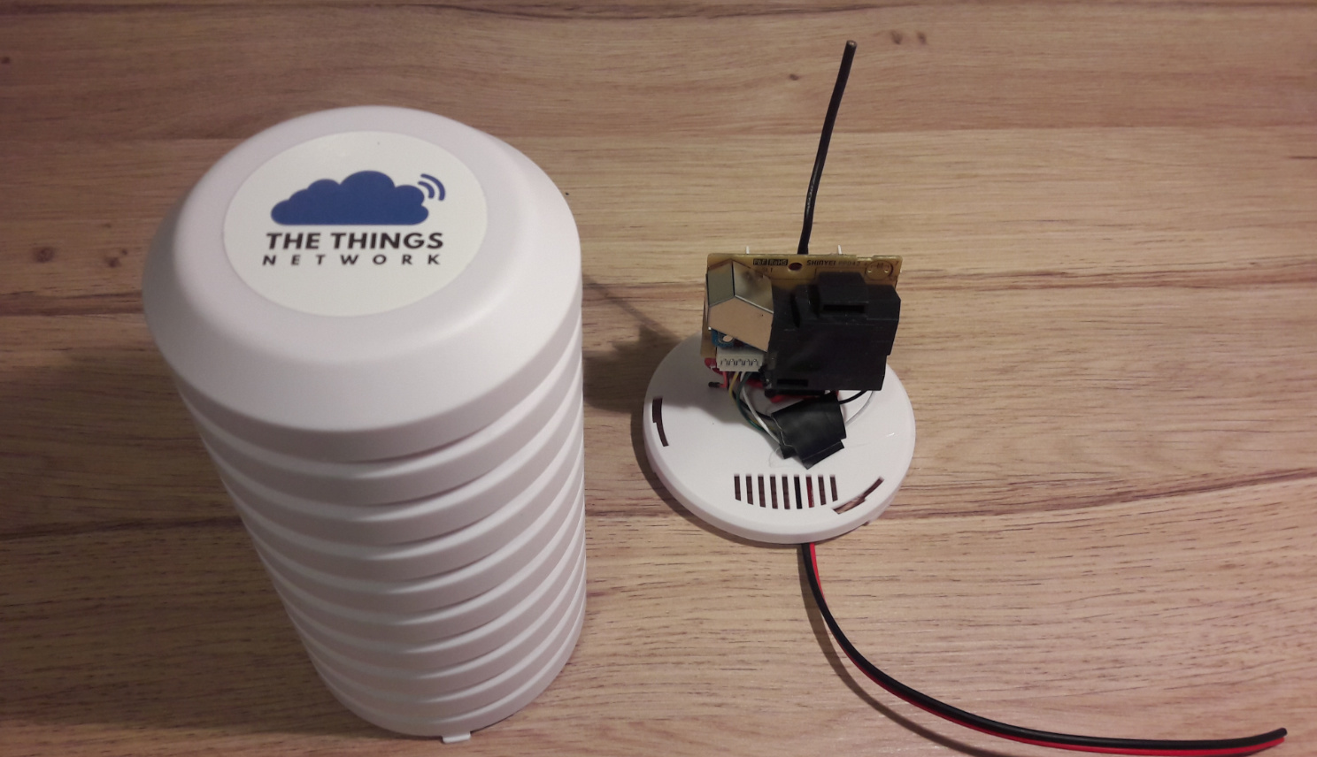
Let’s assume the node to be present. I added a capacitor of 10uF between the RAW and GND. This is because the PPD42NS draws relatively much and without it you could experience power dips resulting in a failure to send. Do not remove the voltage regulator since you need both 5v and 3.3v, but it’s might be good to remove the power led though because else your sensor becomes a glow-in-the-dark thing which may attract vandalism.
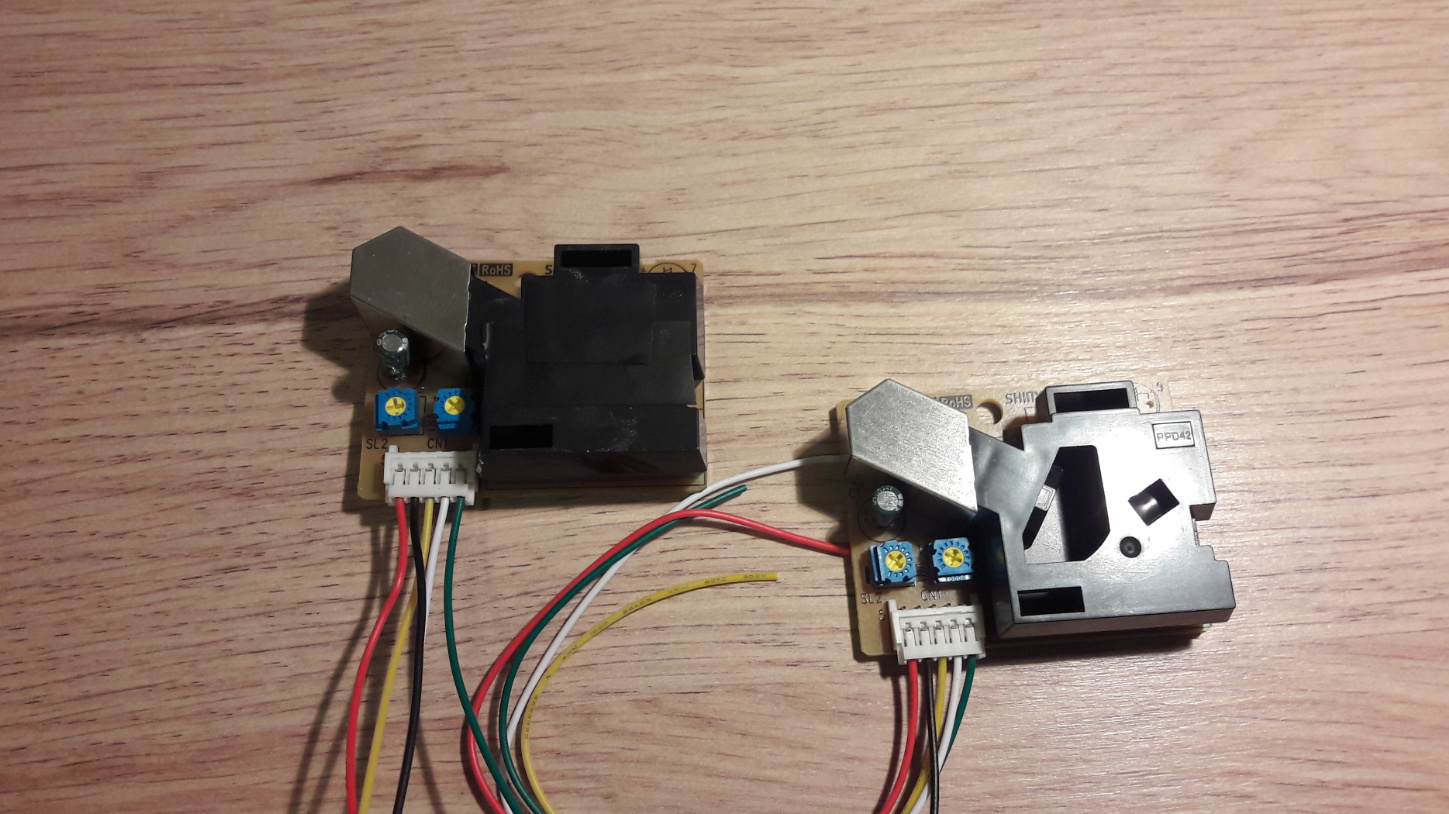
Now we’ll start with the sensor. It has a cleaning hole that needs to be closed with tape as is done on sensor on the left
It’s 5v so it can’t be connected straight to the signal pins of a 3.3v arduino. Although it may work for a while it probably won’t work for long, so we need a level shifter. There are two types, full bidirectional and shifters with also some unidirectional voltage dividers. The one on the pic is of the latter type. In that case you need to use the lines marked with the TX. The RX lines should not be used since they convert the 5v to 2.5v. If anyone is willing to modify the PCB design to include the level shifter on the board please let me know, that would be great!
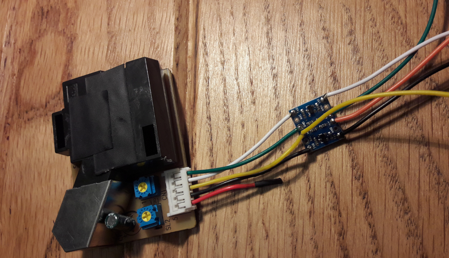
When it’s connected the signal lines can simply be connected to the arduino’s digital pins. The other lines should be connected to the RAW, VCC and GND pins. One is not used, but the wires have stupid color codes so don’t expect something like the red wire to be the VCC.
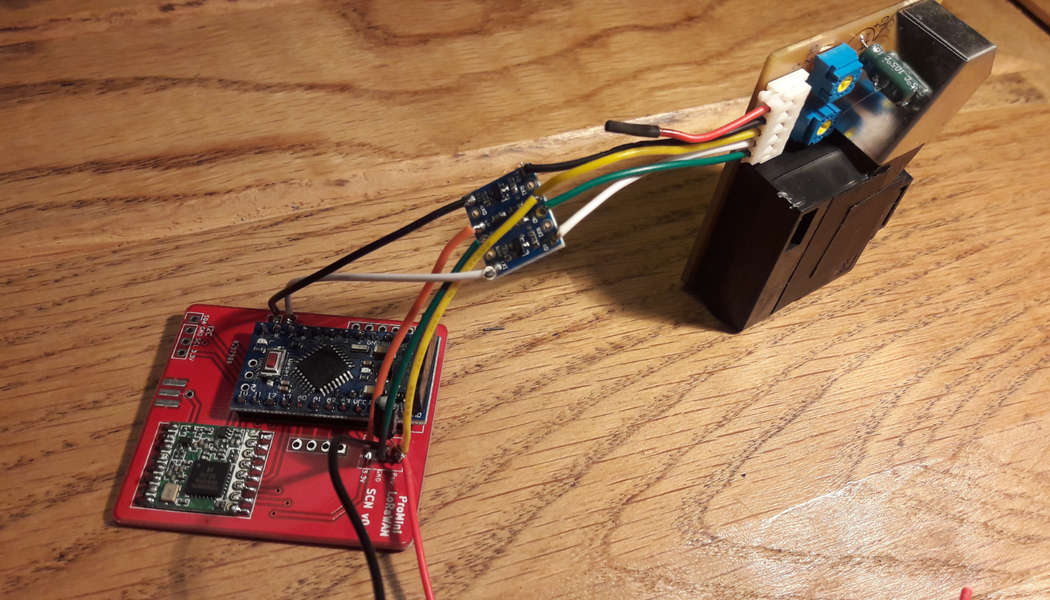
Connect the antenna and mount the assembly to the casing.
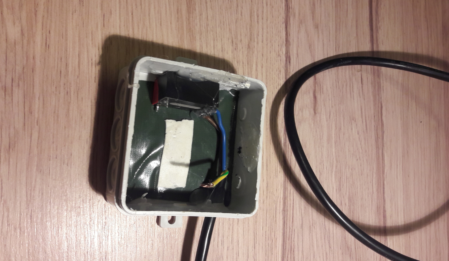
Once this is done the power supply needs to be added. It’s not shown on the picture but the ground wire is connected to the bottom of the box to ground any moisture. I think it’s best to also make the 5v wire go out through the bottom instead of through the top to avoid leakages. Don’t forget to seal it with glue. In a next model I think I’ll build the power supply behind the node PCB, on the other side of the wall where it’s mounted to. In that case sufficient glue is needed to keep everything fully insulated.
Result:
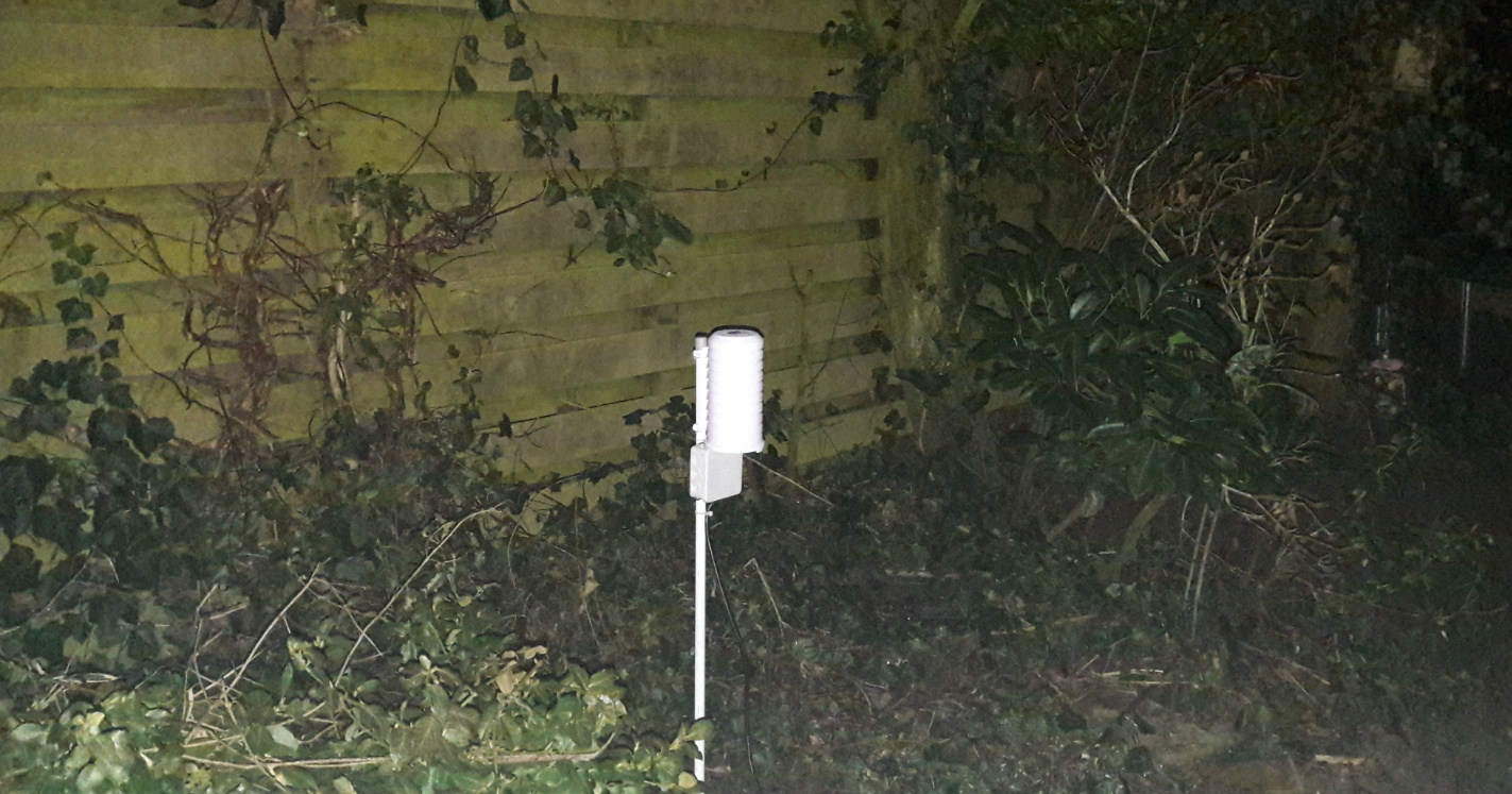
… and this is how it looks like if you don’t remove the power led