This post started as labs story. Because it’s probably because of a bug not possible to upload images I’ll make this a forum topic. Since I don’t want to wait much longer to allow people to start ordering stuff if they would like to join, and feedback is greatly appreciated. I’ll stick to the labs format to make it easier to transfer it one day.
Introduction
We’ve built a LoRaWAN sensor for outdoor use that measures air quality and does so pretty well. It was intended for a local project in Maaspoort, Den Bosch. Recently the Dutch RIVM (National Institute for Health and Environment) distributed 75 of the same sensors with a WiFi connection to investigate how these sensors can be used to gather useful information.
The more, the merrier, so contacts were established and we are now on the way to connect TTN sensors to this RIVM dataset. Of course it’s a great opportunity if we would be able to deploy a broad network of sensors once RIVM is ready to accept external sensors so let’s all join.
And for non-Dutch TTN’ers; even if you can’t connect to this Dutch dataset the thing still works as an independent TTN sensor, and you’ll still benefit from insights possibly found by using large numbers.
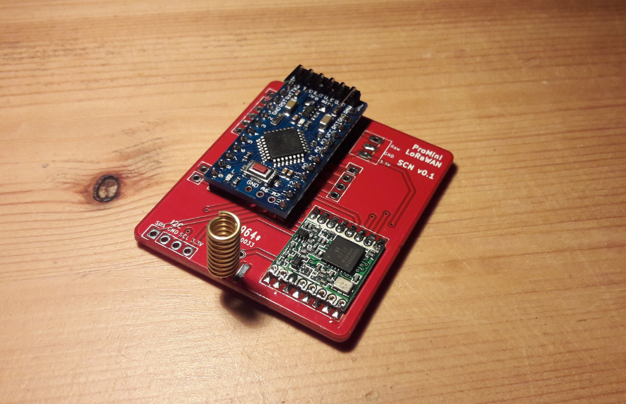
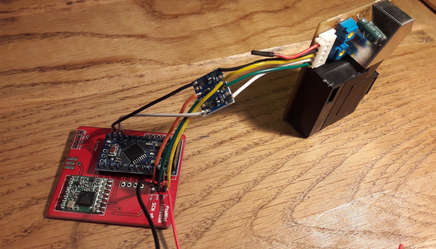
The core components are an arduino/lmic node. This could be the Cheapest Possible Node. Alternatively ready made PCB’s like Doug LaRue’s PCB or LoRaUK’s PCB are also suitable. Alternatively RN2483 based nodes could also be used but that’s out of scope for this story.
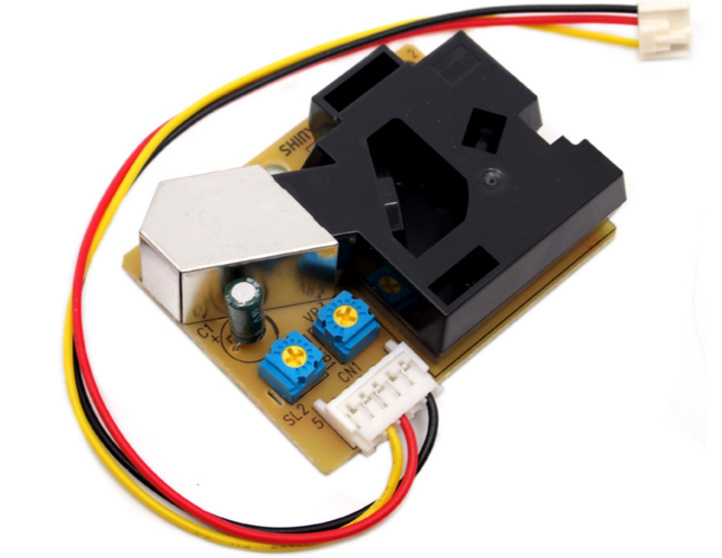
Then you’ll need a Shinyei PPD42NS sensor like used in the DustDuino. Note that because of the need to continuously measure as well as the presence of a heating element this is not suitable for battery operation.
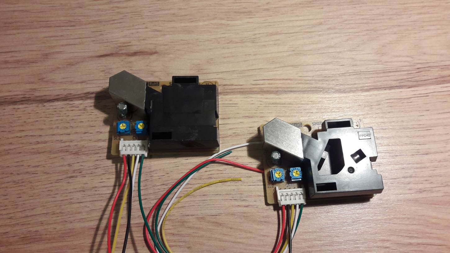
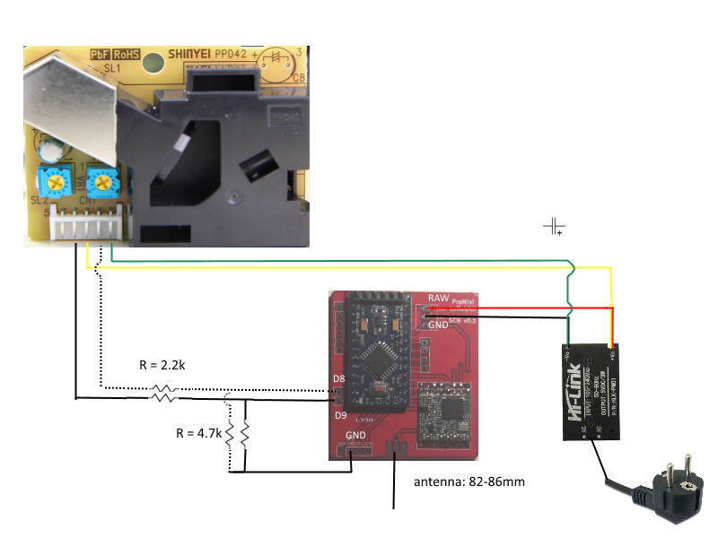
Note: in the newer sensors I’ve built I went to a design with voltage dividers instead of a level shifter. See the wiring diagram below… the pics still show the old situation.
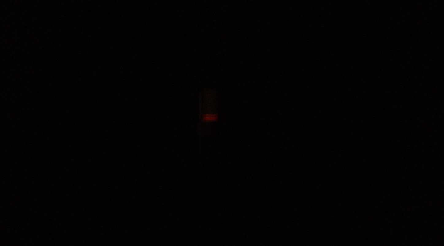
Let’s assume the node to be present. I added a capacitor of 10uF between the RAW and GND. This is because the PPD42NS draws relatively much and without it you could experience power dips resulting in a failure to send. Do not remove the voltage regulator since you need both 5v and 3.3v, but it’s might be good to remove the power led though because else your sensor becomes a glow-in-the-dark thing which may attract vandalism.
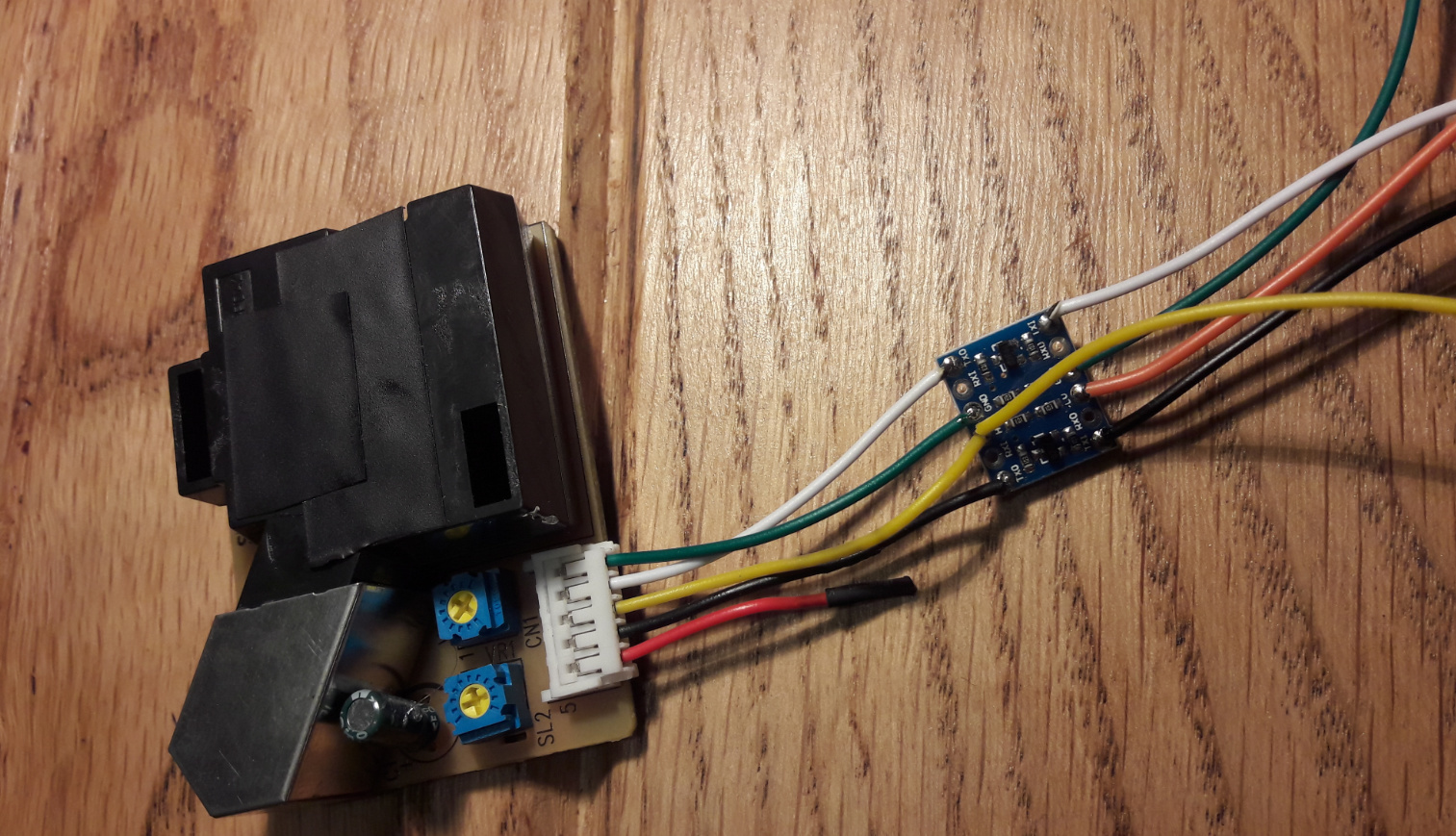
Now we’ll start with the sensor. It has a cleaning hole that needs to be closed with tape as is done on sensor on the left
It’s 5v so it can’t be connected straight to the signal pins of a 3.3v arduino. Although it may work for a while it probably won’t work for long, so we need a level shifter. There are two types, full bidirectional and shifters with also some unidirectional voltage dividers. The one on the pic is of the latter type. In that case you need to use the lines marked with the TX. The RX lines should not be used since they convert the 5v to 2.5v. If anyone is willing to modify the PCB design to include the level shifter on the board please let me know, that would be great!
When it’s connected the signal lines can simply be connected to the arduino’s digital pins. The other lines should be connected to the RAW, VCC and GND pins. One is not used, but the wires have stupid color codes so don’t expect something like the red wire to be the VCC.
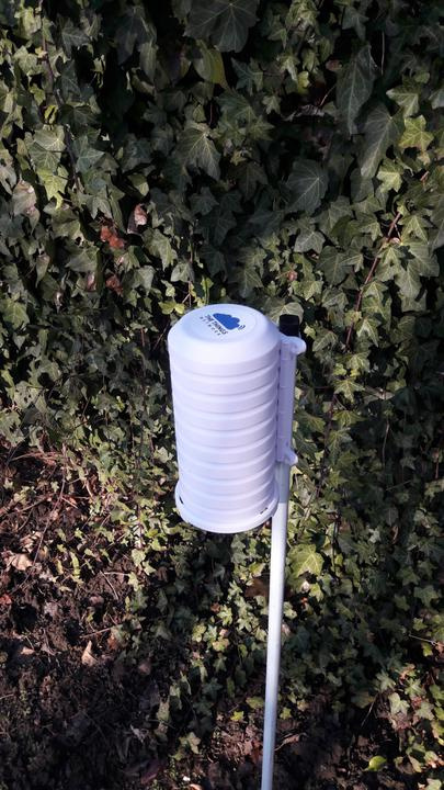
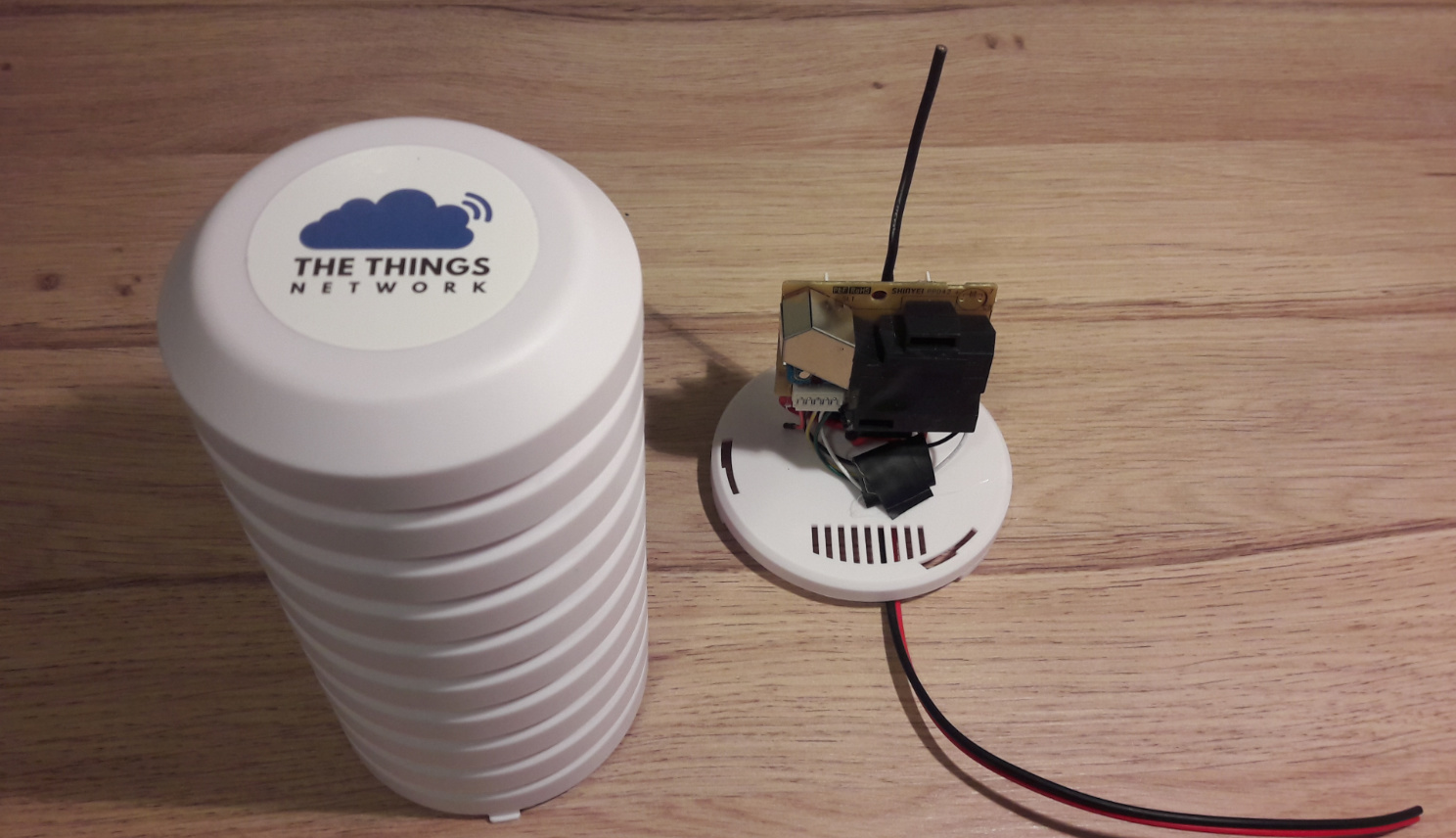
Connect the antenna and mount the assembly to the casing.
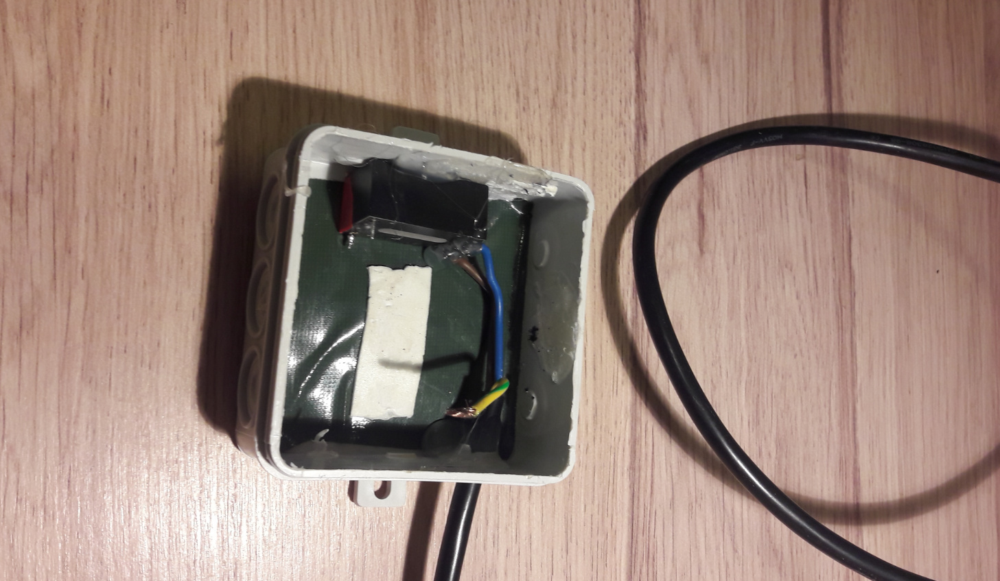
Once this is done the power supply needs to be added. It’s not shown on the picture but the ground wire is connected to the bottom of the box to ground any moisture. I think it’s best to also make the 5v wire go out through the bottom instead of through the top to avoid leakages. Don’t forget to seal it with glue. In a next model I think I’ll build the power supply behind the node PCB, on the other side of the wall where it’s mounted to. In that case sufficient glue is needed to keep everything fully insulated.
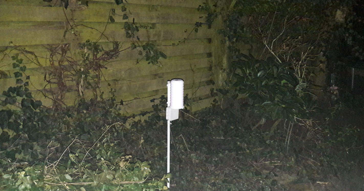
Result:
… and this is how it looks like if you don’t remove the power led
(to be elaborated in detail. The sketch was modified on 7/2, but the old one can be found below. Note that the ‘DLR’ versions will be those with doug larue’s PCB pin layout while those without have the ‘cheapest possible node’ wiring)
For the time being we use a straight forward dashboard which is connected to the TTN application. If you would like to connect your node to it too please contact @jdelaet for credentials and more details.
This is an intermediate solution. I hope that in the next few weeks it becomes clear when RIVM is able to open their network for external sensors. If it won’t take too long that would be a great option and then there’s no need to develop a separate dashboard. If it takes longer we’ll have to look how proceed and build something ourselves.
Modifying the PCB in particular to get rid of the level shifter
Possibly building something to visualize the data
Figure out how to convert the measurement count to actual particle mass. This may need some explanation. The formula from the dustduino doesn’t work on nodes. I suspect that the level shifter has got something to do with it, although it’s not that likely since it’s a digital signal. Another option could be that the LMIC timing/scheduling mechanism does something I can’t explain.
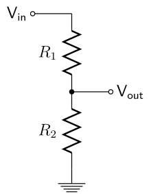
I think the schematics can be simplified be replacing the level shifters with just a simple (two resistor) voltage divider. The pulses from the sensor are relatively slow (5ms to 100ms) so a simple 2k2 + 3k9 divider should work just fine.
Thanks, I got that feedback from some other users too per pm/slack/mail. Initially choose the level shifter because a general thought about this seemed to be that using resistors is a bad practice. This would be because you theoretically would never know what the input would be.
On the other hand this is a digital signal which means you can safely assume it will always be more ore less 5v. I guess it’s correct but I didn’t have time to dig into the subject yet. What I don’t understand though is why you need 2 instead of 1 resistor per line. To my surprise this is what everyone tells me, but could someone explain me why? Wouldn’t one single resistor per line drop the voltage too?
One resitor will only limit the current but not the voltage. So you need a voltage divider using two resitors.
Vin are the 5V pulses from the sensor, using a 2k2 (R1) and a 3k9 (R2) resistor will limit the output voltage (Vout) to a safe 3.2V puls.
I’m wondering why you don’t store the raw (Lo Pulse Occupancy Time) values and do the math (conversion to particle mass) when visualising the data. This makes it more flexible to optimise the conversion (without reprogramming all your nodes).
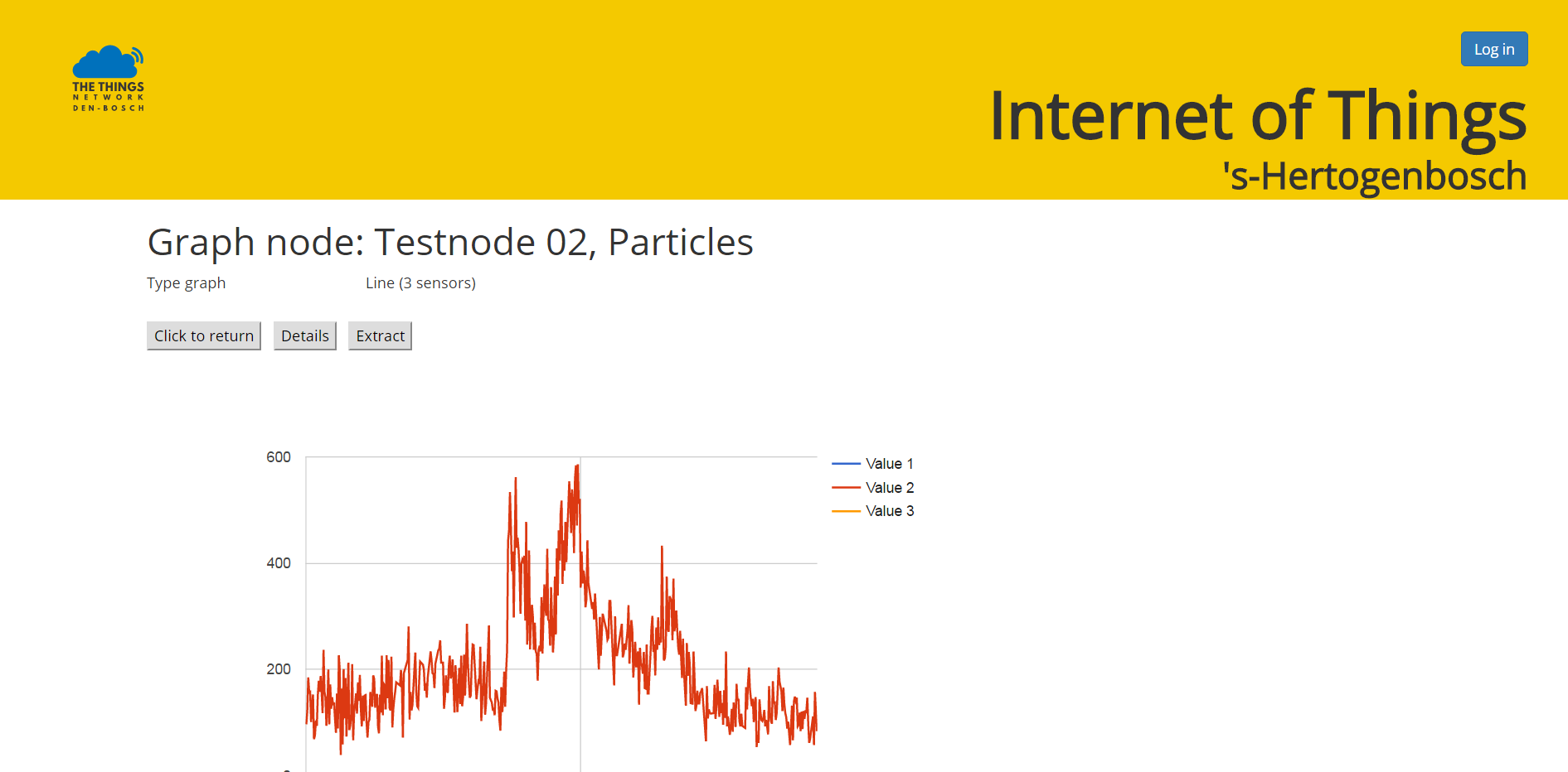
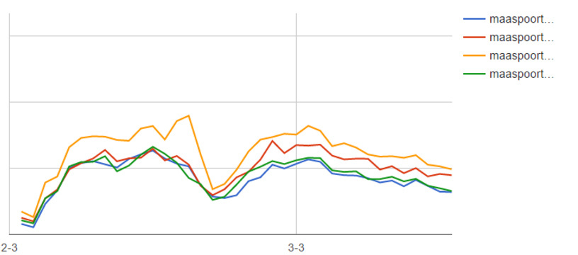
And this is pretty cool. We’re currently in the technical testing phase so we didn’t really pay attention to calibration yet. After deploying 4 sensors in a 100 meter radius this is a snapshot of the result. As you can see the are remarkably consistent, but the yellow sensor is very interesting… this one initially was almost identical with the red one until the tape covering the cleaning hole came off due to moisture. It was then put back again but after that incident it seems to measure more extreme results, so during the next round of maintenance i’ll check if the tape is really still where it should be.
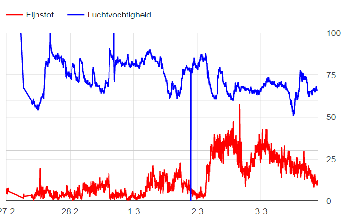
We also fitted two of them with HTU21d temparature/moisture sensors. I’m not sure if it’s really needed but we’ll find out
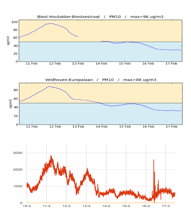
On February 11 and 12 there was a long and high peak in the measurements. Initially I though there was something wrong with the sensors, but then we compared it with 2 RIVM stations 25km away:
They measured the same peak, so our sensors are still fine and it was a real measurement. And then I read this . Great to see our sensors signaled it too.
Do i understood your sketch right, that you turn on the sensor every 33 minutes for 5 minutes and transmit the result? Is the running interval long enough to get a good reading and could it be shortend to lets say 3 minutes or so to reduce power consumption? I ask because i thought about running this sensor from a LiPo (with step up for the sensor) - do you got any data how much mA the sensor uses, or is this totally out of reach?
no, it does measure permanently and every 5 minutes it calculates the result of the measurements and it transmits. Low power is simply impossible with this kind of sensors because regardless any sleep modes on the controller you still need something to maintain an air flow. This could be a serious resistor that gets hot or a fan but whatever you choose it will consume a lot of power
edit: not sure what you’re aiming to measure, but few weeks ago I spoke with someone who tried to use the sharp dust sensor for smoke detection. If that is what you also try to achieve low power would be possible though, because of the high concentrations you don’t need much airflow. Besides that one works with analog readings so I guess you could figure something out with a threshold connected to an interrupt. For air quality measurements it seems to be less suitable though.