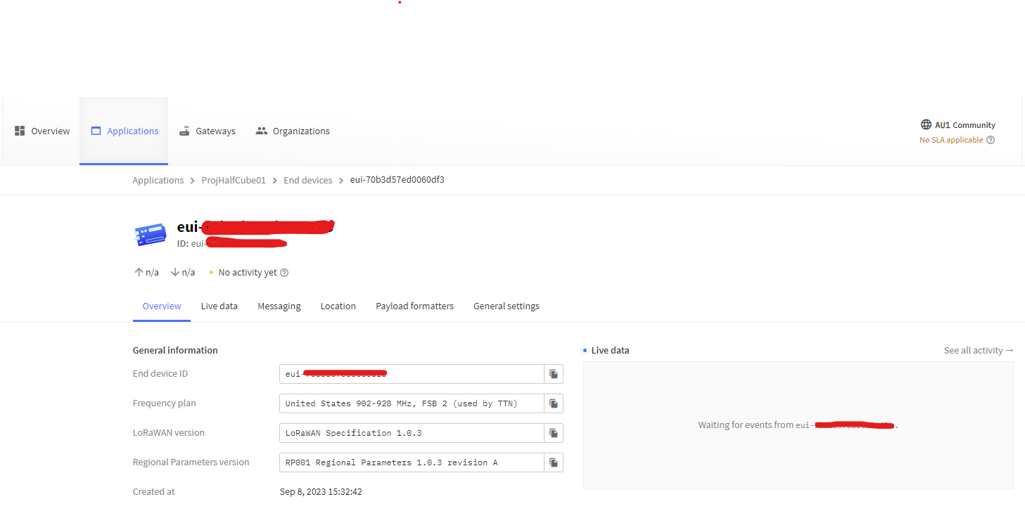
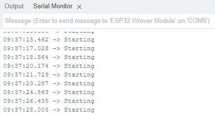
I need help I use the library MCCI LoRaWAN LMIC Library With board ESP32-Wrover. The result is no data sent to TTN Application and when I apply that is used Arduino code Show results that the Unsupported Board. Do I have to fix it by changing the working board?
This is Arduino code that I use;
#include <lmic.h>
#include <hal/hal.h>
#include <SPI.h>
#ifdef COMPILE_REGRESSION_TEST
define FILLMEIN 0
#else
warning “You must replace the values marked FILLMEIN with real values from the TTN control panel!”
define FILLMEIN (#dont edit this, edit the lines that use FILLMEIN)
#endif
static const PROGMEM u1_t NWKSKEY[16] = { FILLMEIN };
static const u1_t PROGMEM APPSKEY[16] = { FILLMEIN };
static const u4_t DEVADDR = FILLMEIN;
void os_getArtEui (u1_t* buf) { }
void os_getDevEui (u1_t* buf) { }
void os_getDevKey (u1_t* buf) { }
static uint8_t mydata = “Hello, world!”;
static osjob_t sendjob;
const unsigned TX_INTERVAL = 60;
const lmic_pinmap lmic_pins = {
.nss = 9,
.rxtx = LMIC_UNUSED_PIN,
.rst = 3,
.dio = {18, 19, LMIC_UNUSED_PIN},
};
void onEvent (ev_t ev) {
Serial.print(os_getTime());
Serial.print(": ");
switch(ev) {
case EV_SCAN_TIMEOUT:
Serial.println(F(“EV_SCAN_TIMEOUT”));
break;
case EV_BEACON_FOUND:
Serial.println(F(“EV_BEACON_FOUND”));
break;
case EV_BEACON_MISSED:
Serial.println(F(“EV_BEACON_MISSED”));
break;
case EV_BEACON_TRACKED:
Serial.println(F(“EV_BEACON_TRACKED”));
break;
case EV_JOINING:
Serial.println(F(“EV_JOINING”));
break;
case EV_JOINED:
Serial.println(F(“EV_JOINED”));
break;
case EV_JOIN_FAILED:
Serial.println(F(“EV_JOIN_FAILED”));
break;
case EV_REJOIN_FAILED:
Serial.println(F(“EV_REJOIN_FAILED”));
break;
case EV_TXCOMPLETE:
Serial.println(F(“EV_TXCOMPLETE (includes waiting for RX windows)”));
if (LMIC.txrxFlags & TXRX_ACK)
Serial.println(F(“Received ack”));
if (LMIC.dataLen) {
Serial.println(F(“Received “));
Serial.println(LMIC.dataLen);
Serial.println(F(” bytes of payload”));
}
os_setTimedCallback(&sendjob, os_getTime()+sec2osticks(TX_INTERVAL), do_send);
break;
case EV_LOST_TSYNC:
Serial.println(F(“EV_LOST_TSYNC”));
break;
case EV_RESET:
Serial.println(F(“EV_RESET”));
break;
case EV_RXCOMPLETE:
Serial.println(F(“EV_RXCOMPLETE”));
break;
case EV_LINK_DEAD:
Serial.println(F(“EV_LINK_DEAD”));
break;
case EV_LINK_ALIVE:
Serial.println(F(“EV_LINK_ALIVE”));
break;
case EV_TXSTART:
Serial.println(F(“EV_TXSTART”));
break;
case EV_TXCANCELED:
Serial.println(F(“EV_TXCANCELED”));
break;
case EV_RXSTART:
break;
case EV_JOIN_TXCOMPLETE:
Serial.println(F(“EV_JOIN_TXCOMPLETE: no JoinAccept”));
break;
default:
Serial.print(F("Unknown event: "));
Serial.println((unsigned) ev);
break;
}
}
void do_send(osjob_t* j){
if (LMIC.opmode & OP_TXRXPEND) {
Serial.println(F(“OP_TXRXPEND, not sending”));
} else {
LMIC_setTxData2(1, mydata, sizeof(mydata)-1, 0);
Serial.println(F(“Packet queued”));
}
}
void setup() {
// pinMode(13, OUTPUT);
// while (!Serial); // wait for Serial to be initialized
Serial.begin(115200);
delay(100); // per sample code on RF_95 test
Serial.println(F(“Starting”));
#ifdef VCC_ENABLE
// For Pinoccio Scout boards
pinMode(VCC_ENABLE, OUTPUT);
digitalWrite(VCC_ENABLE, HIGH);
delay(1000);
#endif

// LMIC init
os_init();

LMIC_reset();

#ifdef PROGMEM

uint8_t appskey[sizeof(APPSKEY)];
uint8_t nwkskey[sizeof(NWKSKEY)];
memcpy_P(appskey, APPSKEY, sizeof(APPSKEY));
memcpy_P(nwkskey, NWKSKEY, sizeof(NWKSKEY));
LMIC_setSession (0x13, DEVADDR, nwkskey, appskey);
#else
// If not running an AVR with PROGMEM, just use the arrays directly
LMIC_setSession (0x13, DEVADDR, NWKSKEY, APPSKEY);
#endif

#if defined(CFG_eu868)

LMIC_setupChannel(0, 868100000, DR_RANGE_MAP(DR_SF12, DR_SF7),  BAND_CENTI);      // g-band
LMIC_setupChannel(1, 868300000, DR_RANGE_MAP(DR_SF12, DR_SF7B), BAND_CENTI);      // g-band
LMIC_setupChannel(2, 868500000, DR_RANGE_MAP(DR_SF12, DR_SF7),  BAND_CENTI);      // g-band
LMIC_setupChannel(3, 867100000, DR_RANGE_MAP(DR_SF12, DR_SF7),  BAND_CENTI);      // g-band
LMIC_setupChannel(4, 867300000, DR_RANGE_MAP(DR_SF12, DR_SF7),  BAND_CENTI);      // g-band
LMIC_setupChannel(5, 867500000, DR_RANGE_MAP(DR_SF12, DR_SF7),  BAND_CENTI);      // g-band
LMIC_setupChannel(6, 867700000, DR_RANGE_MAP(DR_SF12, DR_SF7),  BAND_CENTI);      // g-band
LMIC_setupChannel(7, 867900000, DR_RANGE_MAP(DR_SF12, DR_SF7),  BAND_CENTI);      // g-band
LMIC_setupChannel(8, 868800000, DR_RANGE_MAP(DR_FSK,  DR_FSK),  BAND_MILLI);      // g2-band

#elif defined(CFG_us915) || defined(CFG_au915)

LMIC_selectSubBand(1);
#elif defined(CFG_as923)
#elif defined(CFG_kr920)
#elif defined(CFG_in866)
#else
# error Region not supported
#endif

// Disable link check validation
LMIC_setLinkCheckMode(0);

// TTN uses SF9 for its RX2 window.
LMIC.dn2Dr = DR_SF9;

// Set data rate and transmit power for uplink
LMIC_setDrTxpow(DR_SF7,14);

// Start job
do_send(&sendjob);
}
void loop() {
unsigned long now;
now = millis();
if ((now & 512) != 0) {
Serial.print(now);
digitalWrite(13, HIGH);
}
else {
digitalWrite(13, LOW);
}
os_runloop_once();
}