Big ESP32 + SX127x topic part 3

Maybe, maybe not. The LoRaWAN source used by Heltec is from the original Semtech code base, the people that invented LoRa.

The MCCI LMIC is the continuation of code that has passed through many hands over the years and has proved it’s worth for smaller MCU’s but still has it’s foibles.

Depending on what you are trying to achieve depends on where you go next. If you want to experiment with devices at the LoRaWAN level, then dig in to both code bases. If you want to deploy devices with some useful sensors on, which requires a fair bit of firmware development & testing and get stuck in to the data presentation & analysis, then I’d stick with what’s working. You can of course do both if you have a lot of time on your hand or a really big brain, preferably both.

1 Like

That is a fair result. For a gateway with the antenna indoors distances differ from <100m to a few kilometers but mostly 100-600 meters in my experience. (A lot depends on the materials used in the building)

1 Like

Friends:
I am using a TTGO v1 with a DTH11 sensor to send temperature and humidity, I use the MCCI_LoRaWAN_LMIC library
with version 1.5.1, using the example ttn-abp-feather-us915-dht22.
I use the V3 of TTN for the new changes for 2021.
I have 2 gateways (one channel) and both the sending node and the receiving node (903.9 MHz) channel 0 are configured on the same frequency.
However, I get these errors and the data is not uploaded to the platform.
Could someone help me, maybe something needs to be changed in the library or in the TTGO programming? GATEWAY-NUEVO1 GATEWAY-RPI

I’m sorry for you but we do not support single channel packet forwarders on the forum.

See: Single Channel Packet Forwarders (SCPF) are obsolete and not supported

1 Like

thanks.

<rant-mode>

Some examples of inconsistencies in LilyGO/TTGO documentation.

In this case for TTGO LoRa32 V1.3 (aka LoRa V1.3, aka T3 V1.3).

Part of the circuit diagram:

Notice that the LoRa32 V1.3 circuit diagram is actually placed in the T-Beam repository which is a totally different product. The information is not where one expects and will try to look for it.
LilyGo also have a website which unfortunately hardly provides (better detailed) information about their (LoRa) products and is again made difficult to find.

TTGO T3 V1.3 partial circuit diagram

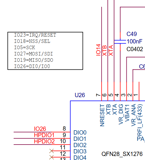
What the above says:
SX1276 Reset is connected to ESP32 GPIO14 (diagram)
SX1276 Reset is connected to ESP32 GPIO23 (textbox)
Only one of these is correct. Now you figure out which one…

The information in the textbox shows “IO23 = IRQ/RESET” but IRQ and Reset are not the same and do not use the same pin!
What is often incorrectly called IRQ on these boards is actually the DIO0 pin from the LoRa chip which on TTGO LoRaWAN boards is connected to the ESP32’s GPIO26 pin and not GPIO23.


TTGO T3 V1.3 partial circuit diagram (2)

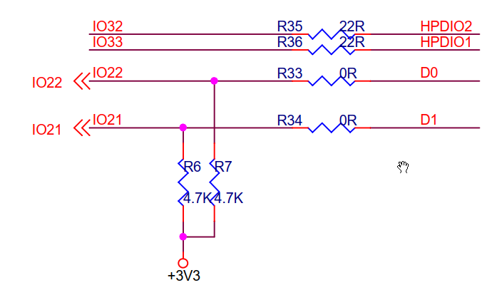
According to the circuit diagram:
Display D1 is I2C SDA = ESP32 GPIO21
Display D0 is I2C SCL = ESP32 GPIO22

However, in practice this appears not to be true,and instead:
SDA = GPIO4
SCL = GPIO15


The same repository contains a product link for the TTGO LoRa32 V1.3 that points to the LilyGo shop on AliExpress (in Portugese!).
The page contains a pinout diagram for the TTGO LoRa32 V1.3 (aka T3) that contains the same incorrect?? I2C pins information:

TTGO T3 V1.3 I2C pins (1)

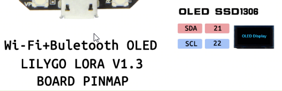
A month ago I copied the same pinout diagram and then it showed:

TTGO T3 V1.3 I2C pins (2)

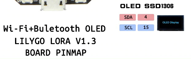
As said before, in posts from others SDA in pratice appears to be GPIO4 and SCL appears to be GPIO15. Which is as shown on the pinout diagram from a month ago, while the pinout currently shown on their shop’s product page shows SDA = GPIO21 and SCL = GPIO22.
I don’t have the board so I am unable to verify it.

The different pinout diagrams do not show a document version or document date.


What to believe here? Who / what is correct and when?

Without actually having the boards to verify it is impossible to know which information is correct.

Will we soon see a batch of new boards with same version number where the IC2 pins have suddenly changed?


Deficient documentation and contradicting information like above make it hard to keep information in this topic up to date and reliable (and this hasn’t improved much over time).

It also does not give much confidence in these products. If essential information and documentation keep having/getting errors and inconsistencies then why would one expect the products themselves and their design to be any better?

</rant-mode>

Do you have to set anything in software to set the AXP chip to allow the On button to work?

I’m aware it has to be held down for a few seconds, so it’s not that. Nor is it a flat battery.

It might be useful to provide a little more information. :wink:

What device is this about?
Do you mean AXP192 on a TTGO T-Beam?
Which version?
(The T-Beam topic might even be a better place to post it.)

What code have you used to initialize the AXP?

Yeah, not fully awake, will try there.

If you mean the user button connected to GPIO38:

You will need to setup the 3.3V line on the AXP first to make the button work.

See my post in the T-Beam topic.

No, I meant the PWR button, now I’ve looked at it again. Still not awake so I’ll leave it alone and ask on the other topic later on after the coffee has cut in.

The topic start has been updated with information about TTGO T-Beam.

I have a TTGO LoRa32 V1.0, I want to use it with DTH11 to measure temperature and humidity, but I have problems because I can’t find an example with the programming code to make it work, because I don’t know which version works for the working frequency ( 902-915 MHz) and what version of the ILMIC library should be used for the node to work in ABP mode for TTN V3 ???

Most information is already available at the start of this topic. Just read it. The library advised to use is also the library most suitable for V3.

It also describes which examples to start with, (but those do not include use of a temperature sensor).

Use of ABP with V3 is possible but not preferred. Use of OTAA is preferred.

Check/search the forum and ‘V2 to V3 upgrade’ category for important information about how to migrate devices to V3.

Hi there,
Im new to this forum. I think I got a simple question.
Can you implement OTAA/ABP comms with a TTGO/Heltec (etc), the LMIC Library and the device EUI, app key etc from another server/host apart from TTN? Or does it just works with the TTN network?
Thanks in advance <3

You should be able to use the TTGO on a private (non TTN) network, but perhaps thats a question for the support forum of the private network you had in mind,.

The problem is that there are different versions of the lmic library. I have tried some and they give me errors, in addition to making several changes in working frequencies (in the sub libraries), among other things, that is why it is my question to know if someone already has a system with this temperature sensor ( very common) to be able to replicate more easily and to avoid errors. Thanks

Heltec devices are now available in the LoRaWAN Device Repository

Heltec has added their LoRa devices to the LoRaWAN Device Repository.

This means that these devices can now be selected from the device list when adding a new device in the V3 Console.

2 Likes

The latest version of Arduino Core ESP32 now has additional boards added. Finally also additions for TTGO LoRa32 V2.x.x boards:

  • ttgo-lora32-v2
  • ttgo-lora32-v21new

For Heltec boards the Wireless Stick and Wireless Stick Lite were added already earlier:

  • heltec_wireless_stick
  • heltec_wireless_stick_lite

As usual, don’t blindly trust board definitions in the Arduino cores:

I noticed an error in the ttgo-lora32-v21new BSP:

#define LORA_RST 12 // GPIO14 - SX1276 RST

But uh, oh, LoRa reset for this board is connected to GPIO23
(Well, at least according to LilyGO’s pinout diagram for this board.)

And similar error in the ttgo-lora32-v2 BSP:

#define LORA_RST 12 // GPIO14 - SX1276 RST

The same ‘12 commented as 14’. However, in reality LoRa reset on the
v2.0 board board is NOT connected to any GPIO but to EN/RST of the ESP32…

I wonder what people are creating these board definitions.
How hard can it be to check consistency between code, comments and reality and correct any errors before this stuff gets released globally to thousands of users?

The topic-start has been updated with the LMIC-node example and a link to the pinout-diagrams repository which contains pinout diagrams for most of the boards described in this topic. In addition some notes were added for The Things Stack V3.

2 Likes