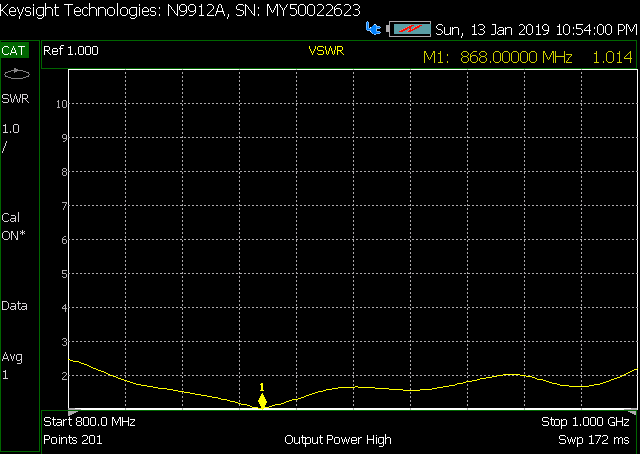
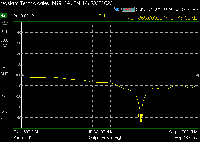
IMPORTANT NOTE : When I build the antenna I used a cable which I would use to install the antenne outdoor and mounted the for testing on a wood kabinet it was almost perfect. Installed at my home and connected to my gateway it seemed to work out fine (on long distance slightly better RSSI).
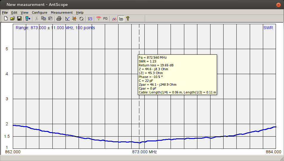
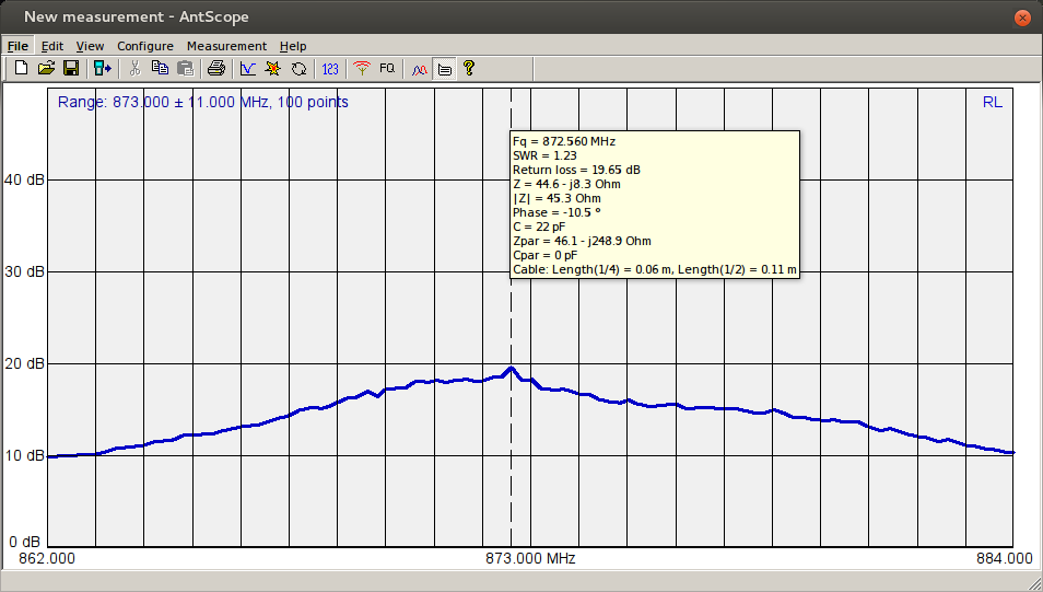
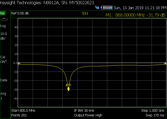
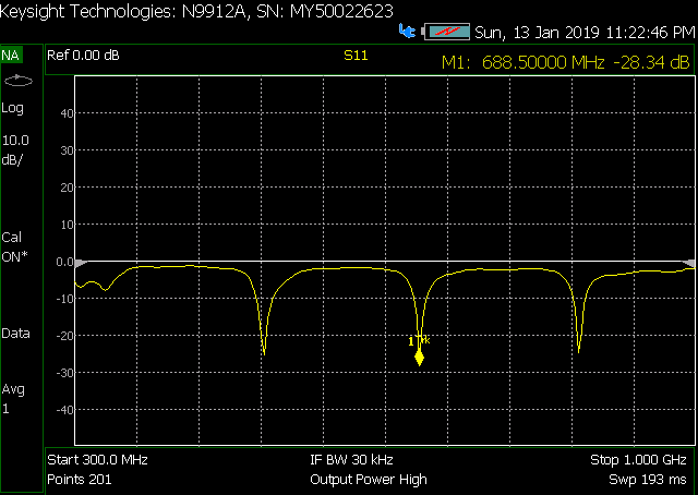
This evening we where testing the 2 antenna’s I build and found out that the antenne design is highly effected by the length of the cable and installation style (using a metal tube to mount it to, metal roof underneed etc). We used the same antenna with a 1.5 m long cable (same cable type, connectors etc) and it shifted 5Mhz up.
So there is rework to do in the design.
So I will modify the LAB indicating its a experimental antenna which is unstable at the moment. When people want to build a outdoor antenna, go for the simple ground plane or read this topic on how to use a indoor antenna outside.
I am in Malaysia Lumpur and I can find stuff on lazada or in the market called Pudu plaza. That area has many electronics shops and a few shops for RF and antennas
ok, seen
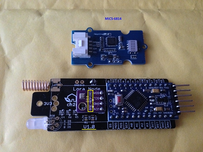
I’ll use at the moment the helical antenna with good results. see
long distance tests will follow, when the program runs with downlink and ack too.
I made a version of this antenna, but with slightly different dimensions found here:
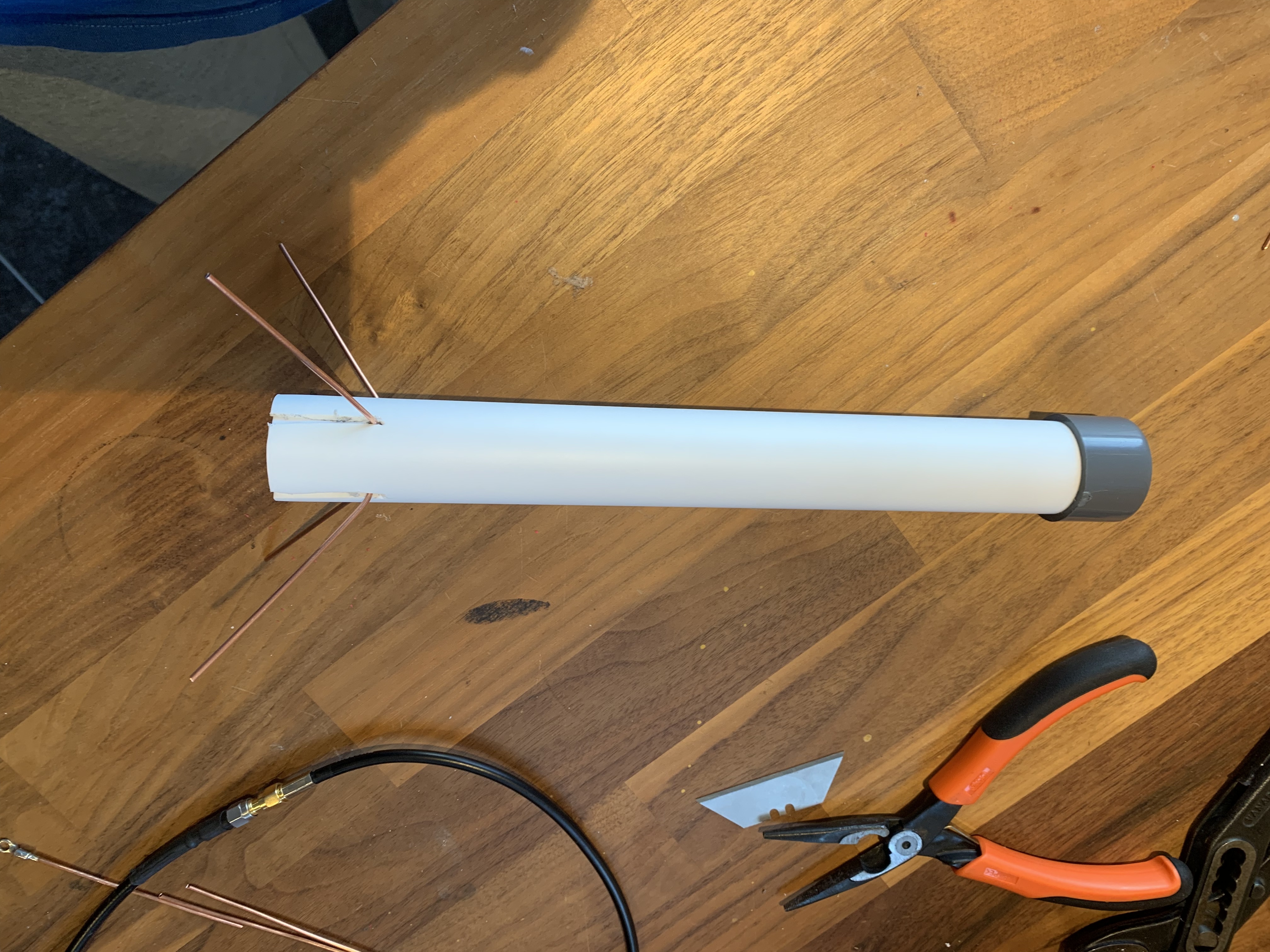
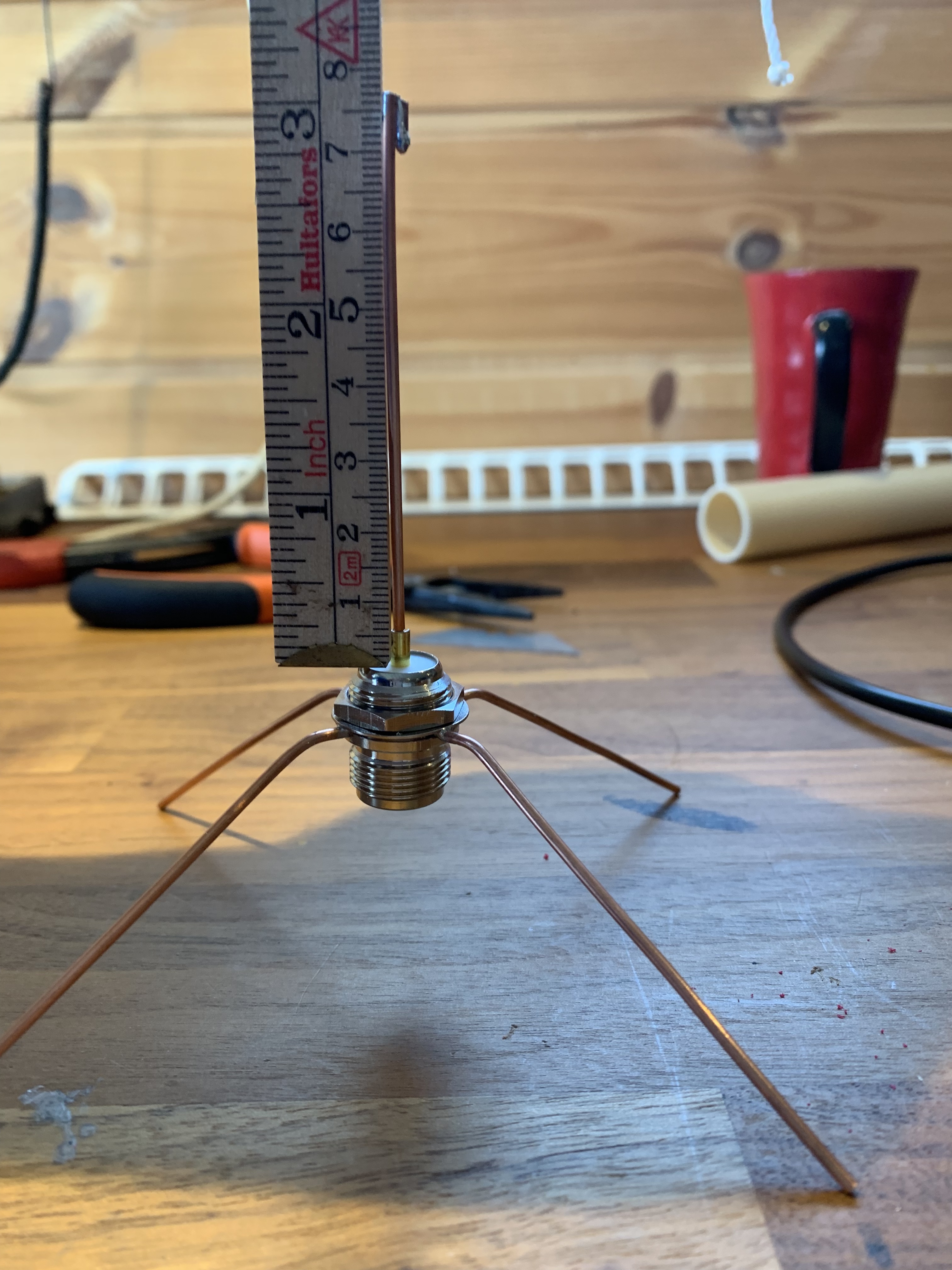
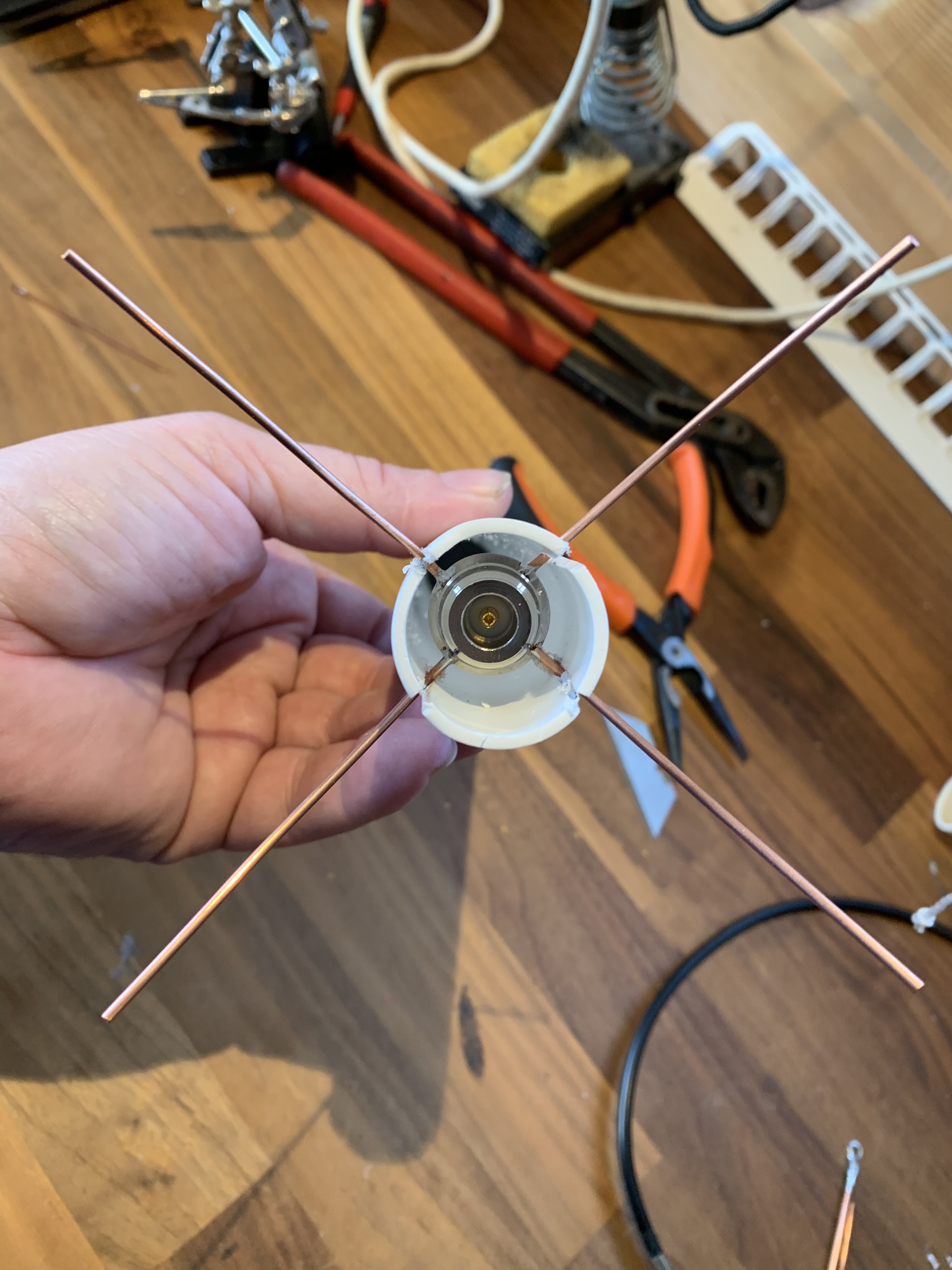
I also added ground plane, as I read somewhere that that is a good idea. I used 1,6mm diameter single copper wire and 32mm PE drain pipe. I cut grooves in in the drain pipe to get the circular N chassis connector with the ground plane wires sticking out. Then cut a small piece, approx 20mm with a groove, to use as insert to hold the antenna in place, but also to strenghten. I plan to use a joint to extend the pole with the antennae cable going inside. It will be 2 meter cable in to the gateway at my loft.
Next step is to try both antennas and see how they perform using a node.
Maybe I will try the J pole as well, but from what I have read, the Ground plane or Collinear seems to be good.
Make sure your ‘drain pipes’ are RF transparent as though you have worked hard on the electrical matching & tuning many pipes you can buy in diy/plumbing supply shops can be poor RF performers due to materials used, metallic contaminants or use of recycled plastics …just a heads up!
@jeff-uk Thank you for the advice. I first made one using 32mm piping for electric wiring. I thought that would be good as it had only approx 0,5mm WT, compared to the drain pipe which is approx 1mm. Unfortunately when I cut a 10cm piece and put in the microwave it got hot, then the microwave oven died on me! The oven was over 25 year old so I guess it has done it’s job:) The drain pipe is soft, clear white PE, I belive, but I have not been able to test it as I no longer have a uW oven. On the Collinear the pipe made a big jump in resonance frequency, which makes me think it is not that good. I actually planned to use a glass fiber rod and glue to antenna to it and leave it open, perhaps spray it with plastic spray, but decided against it.


