How to build your first TTN node: Arduino + RN2483

There is a lot of information distributed across this forum on how to build nodes for TTN. I’m going to summarize how I built my first TTN node using an Arduino Uno and an RN2483 radio module. See this as a “How to get started” tutorial for first time builders. There are a lot of things this design can improve on, but this is at least a good place to start.

What you will need:

Steps:

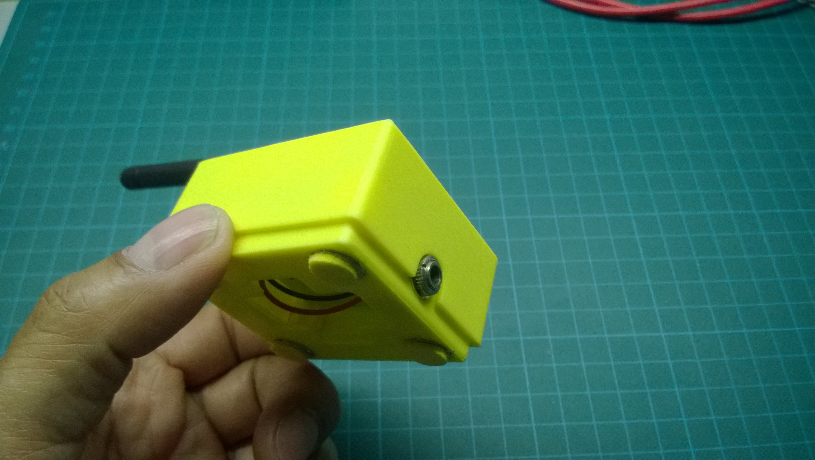
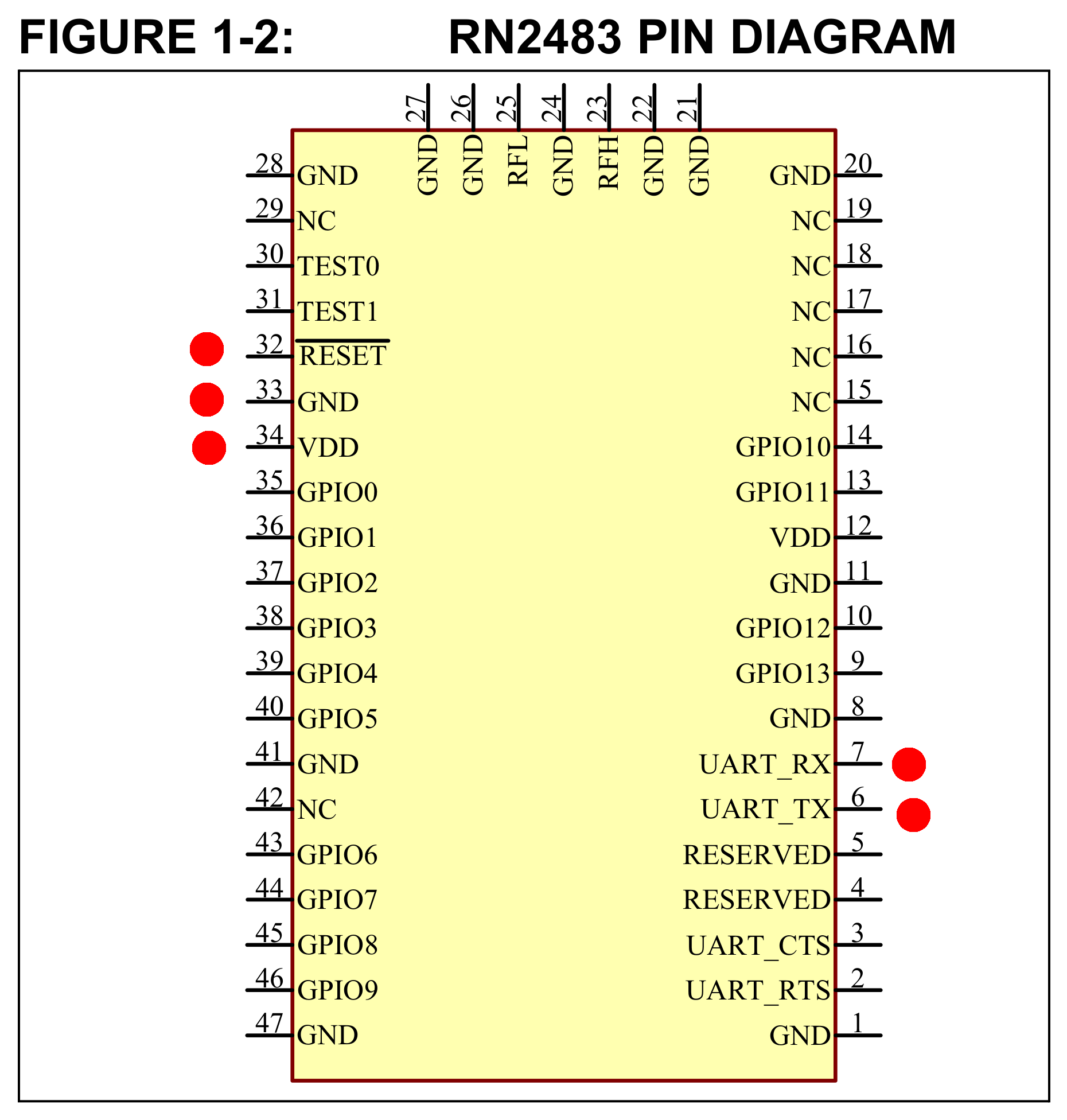
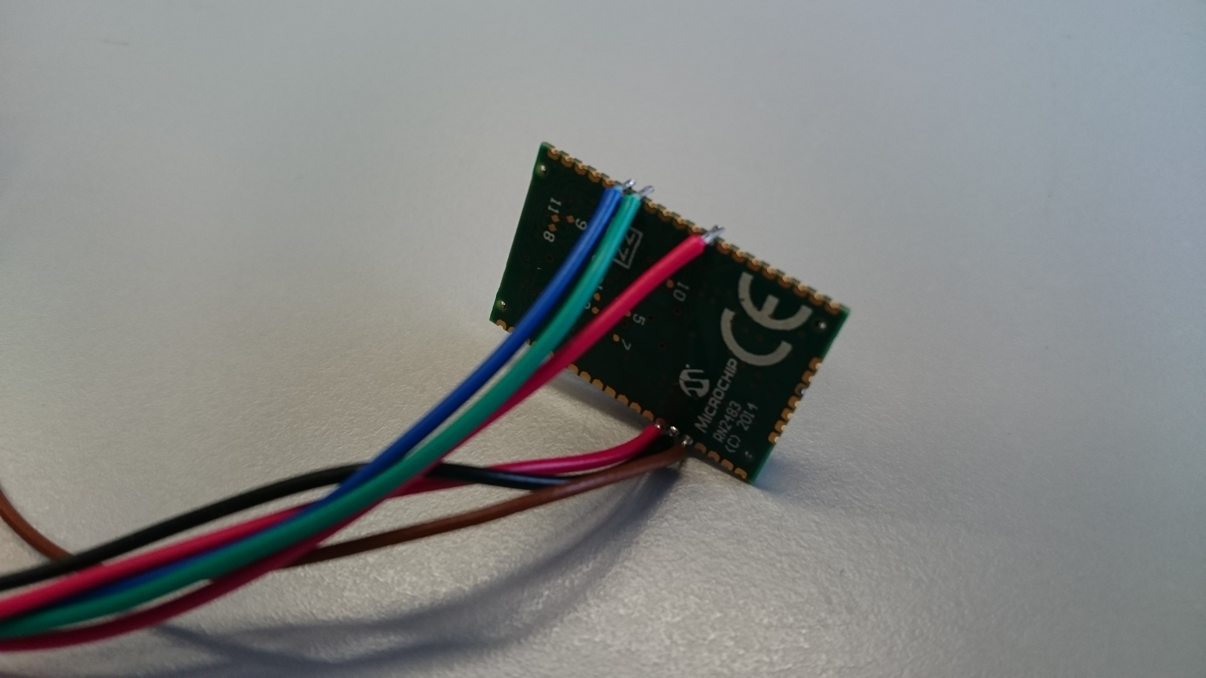
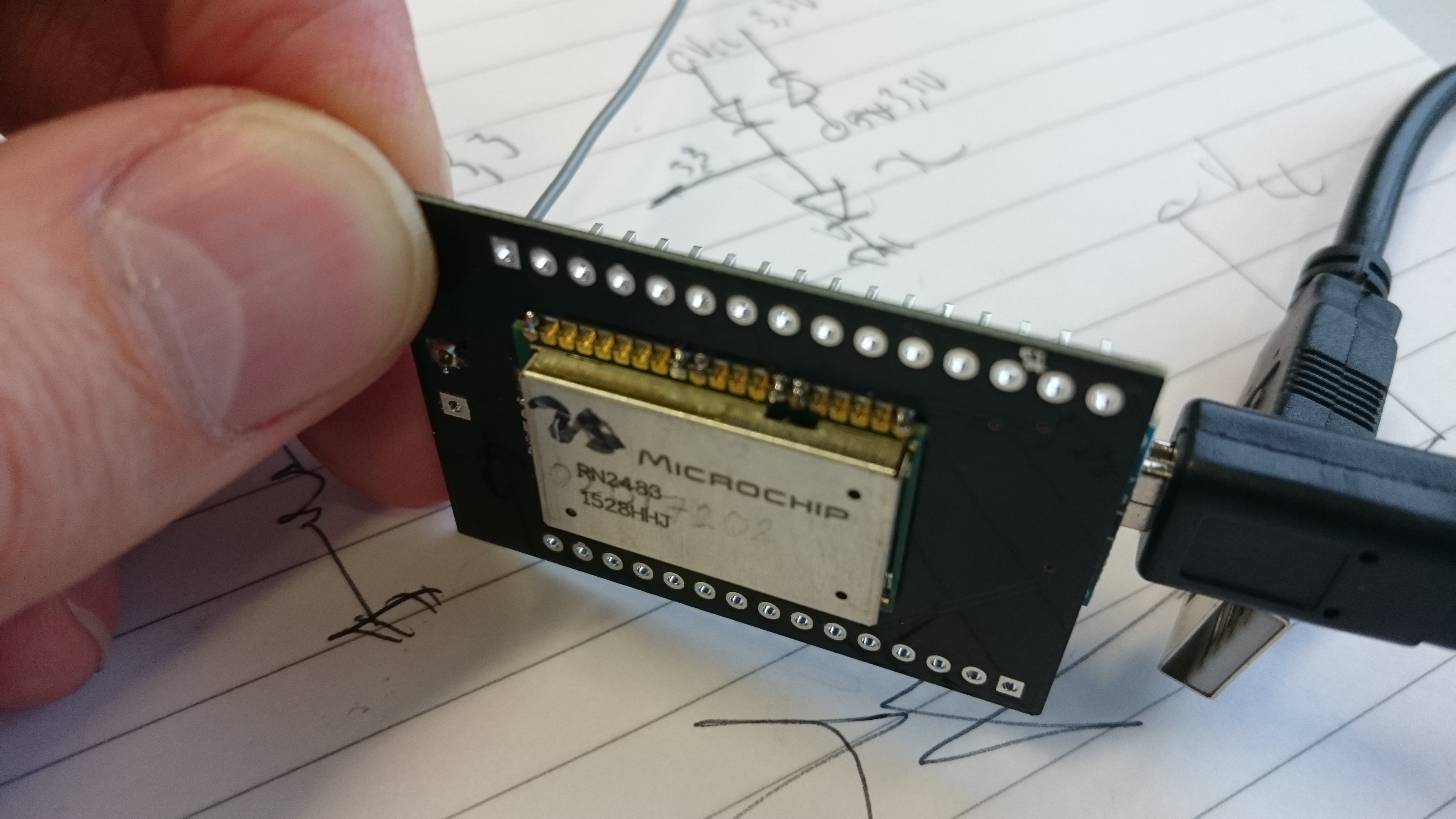
Solder wires to the pins marked with red dots in the top view diagram below. It is better to use stranded wire, as solid core wire tends to easily break off when you solder directly to the radio’s pins. An alternative way is to use VeroBoard.

You might also want to add a 8.6cm piece of wire to pin 23 (RFH) to act as antenna. Solid core wire does however work better in this case to keep the antenna straight.

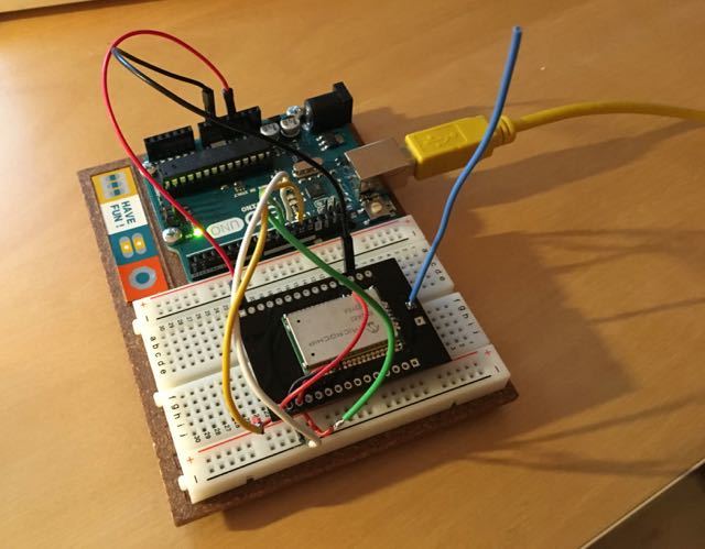
An example of how I did this can be seen in the following photo:

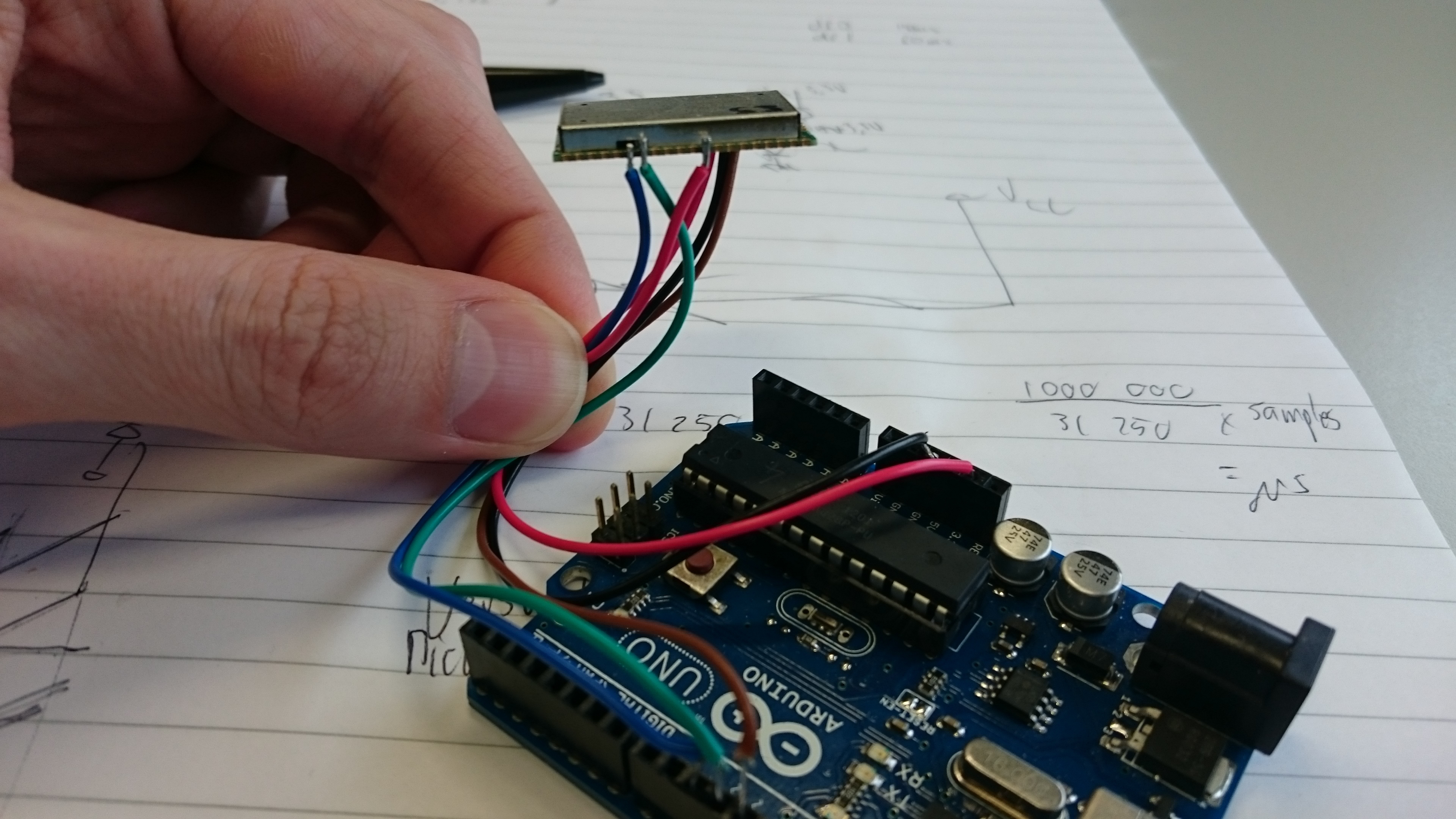
Now connect the RN2483’s wires to the Arduino like this:

RN2483 pin name <--> Arduino pin number
  UART_TX (6)   <-->   10
  UART_RX (7)   <-->   11
  RESET (32)    <-->   12
  VDD (34)      <-->   3.3V
  GND (33)      <-->   Gnd

In my case it looks like this:

Next on to the software side.
Download the zip file containing the code from my github repository: https://github.com/jpmeijers/RN2483-Arduino-Library

Follow the steps to install an Arduino library.

After you installed the library, in your Arduino IDE you can go to File -> Examples -> RN2483 Arduino Library -> ArduinoUnoNano-basic

On the TTN Dashboard which is currently available at https://staging.thethingsnetwork.org, register a new application and a new device. My advice is to use ABP for your first node. After creating it, enable “relax frame counter”.

Around line 87 in the example sketch you opened earlier you will see lines looking like:

  //ABP: initABP("Dev Address", "App Session Key", "Network Session Key");
  join_result = myLora.initABP("02017201", "8D7FFEF938589D95AAD928C2E2E7E48F", "AE17E567AECC8787F749A62F5541D522");
  
  //OTAA: initOTAA("App EUI", "App Key");
  //join_result = myLora.initOTAA("70B3D57ED00001A6", "A23C96EE13804963F8C2BD6285448198");

In the comments above both lines the values that should be filled in between braces are described. If you registered a node as ABP on the TTN Dashboard, you have to uncomment the initABP line, and copy the correct keys from the dashboard into the Arduino sketch. Note that this is a hexadecimal value, so only numbers (0-9) and the capital letters A-F are valid. The strings should not contain any other characters. Use the example keys in the sketch as guideline what it should look like.

Program the code onto your Arduino. If it runs, the LED on the Arduino should be constantly on, except for going out for 100ms once every 5s. This means it is transmitting packets to TTN. If you do not see this behaviour, check your wiring.

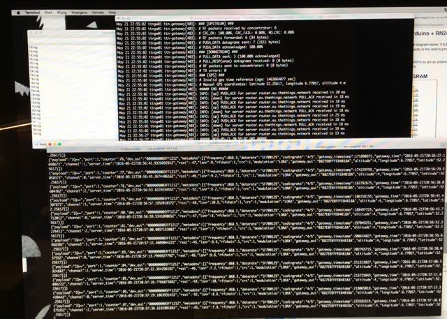
If you are in the reach of a TTN gateway, you should now see your messages arriving on the dashboard.

You should have your first working TTN node now. Change the code, experiment, and let us know what you built!

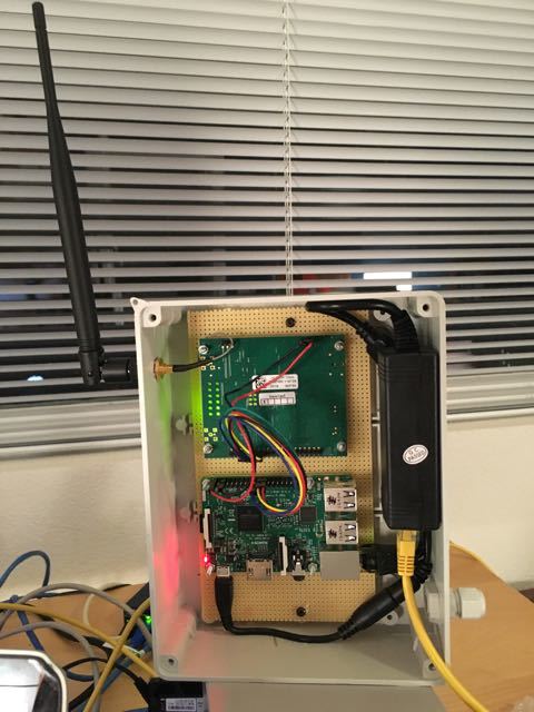
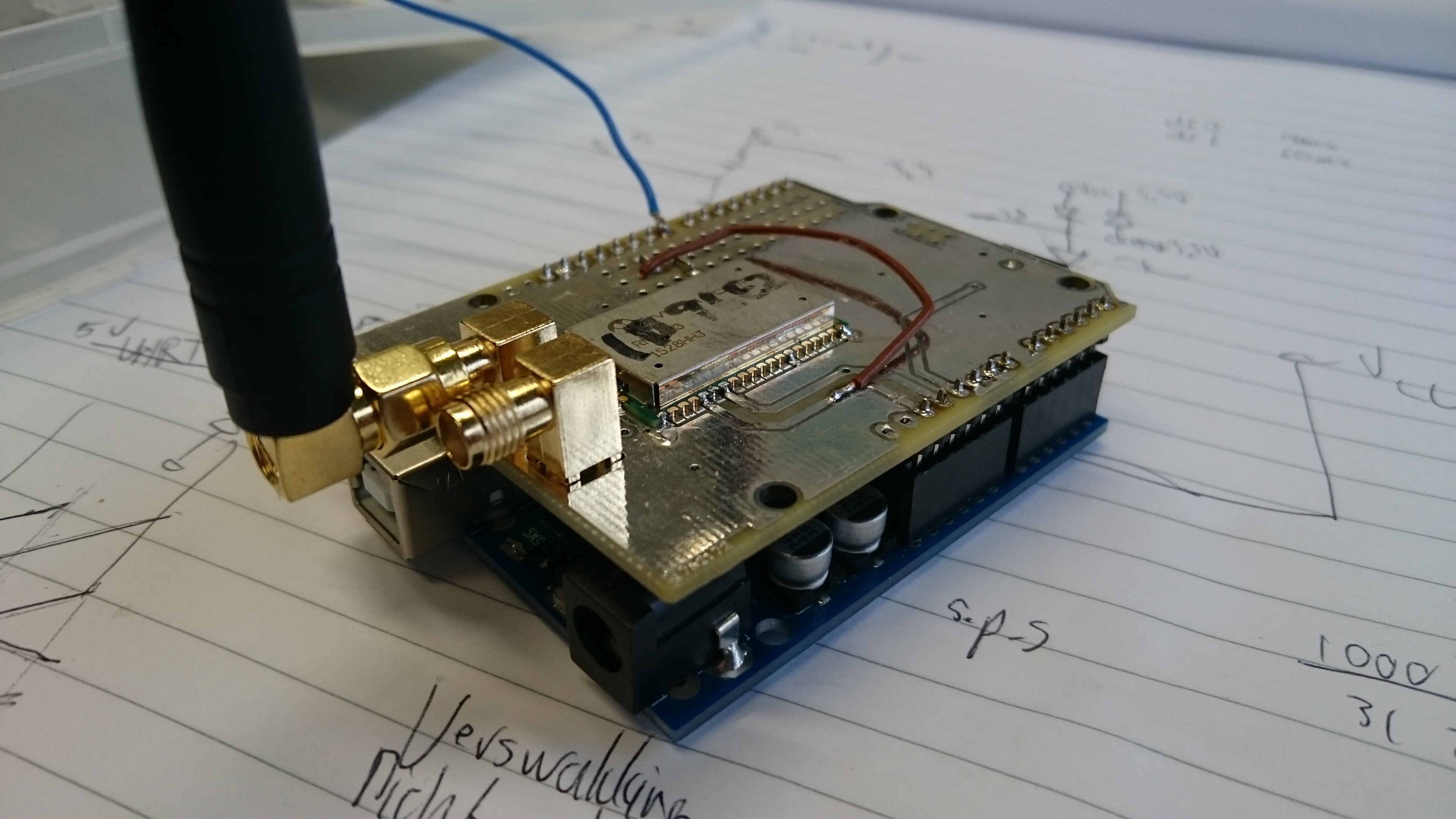
Some more examples of my improvements to the Arduino+RN2483 combination:

Arduino Uno with RN2483 shield. The design of the shield is on my Github page.

Arduino Nano, surfacemounted on one side, with the RN2483 on the other side. I can provide this PCB design if someone needs it.

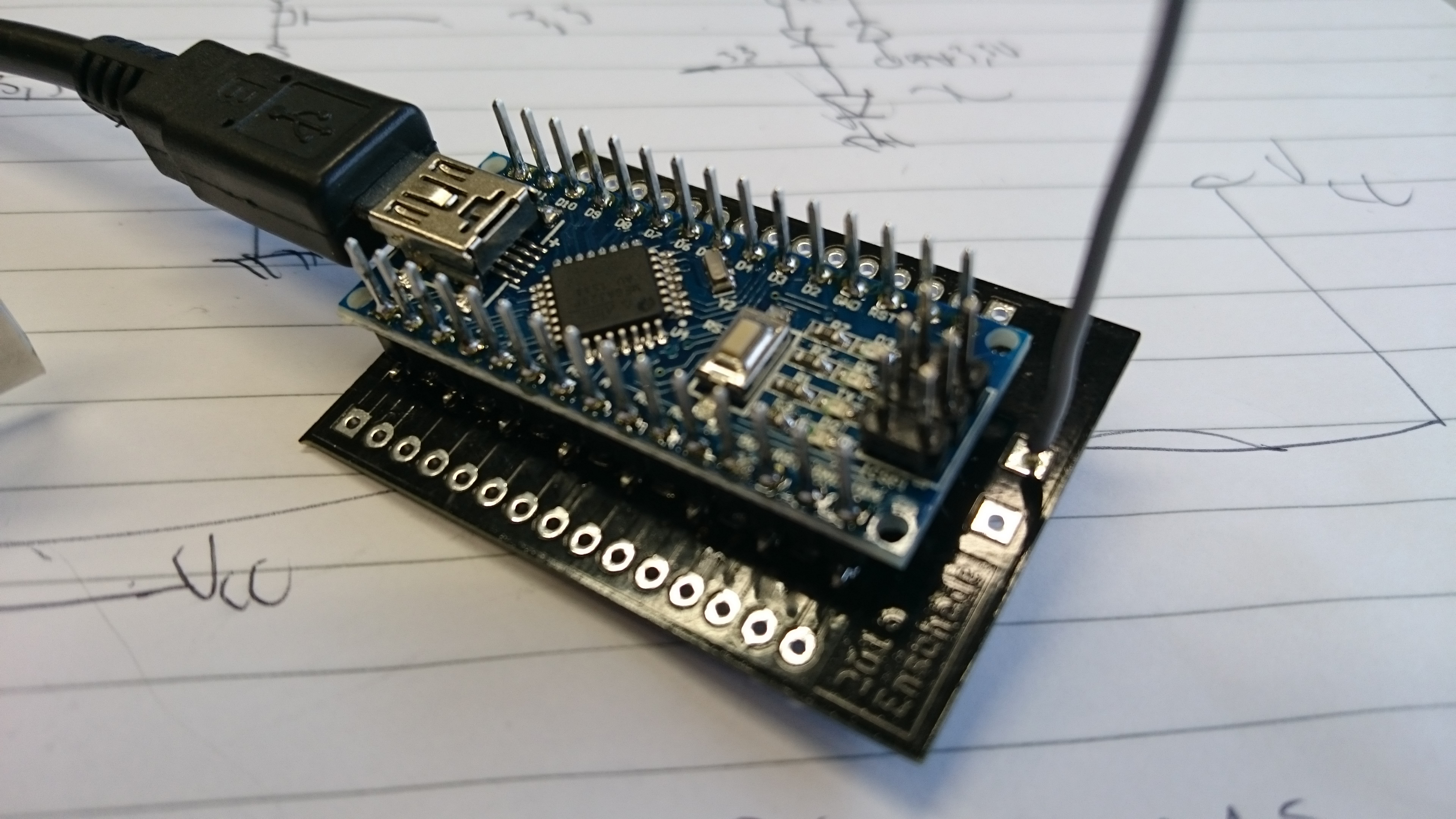
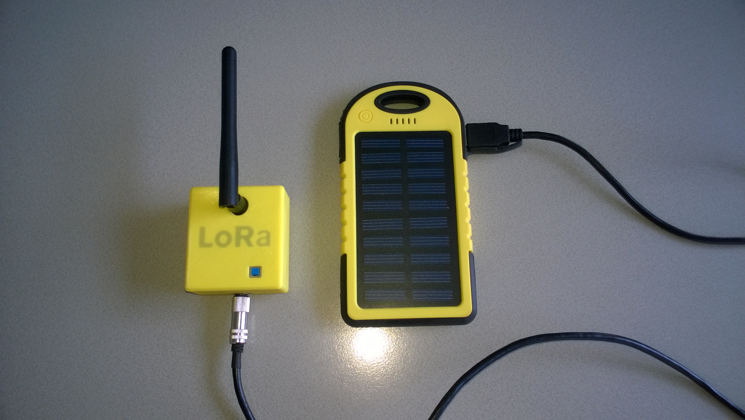
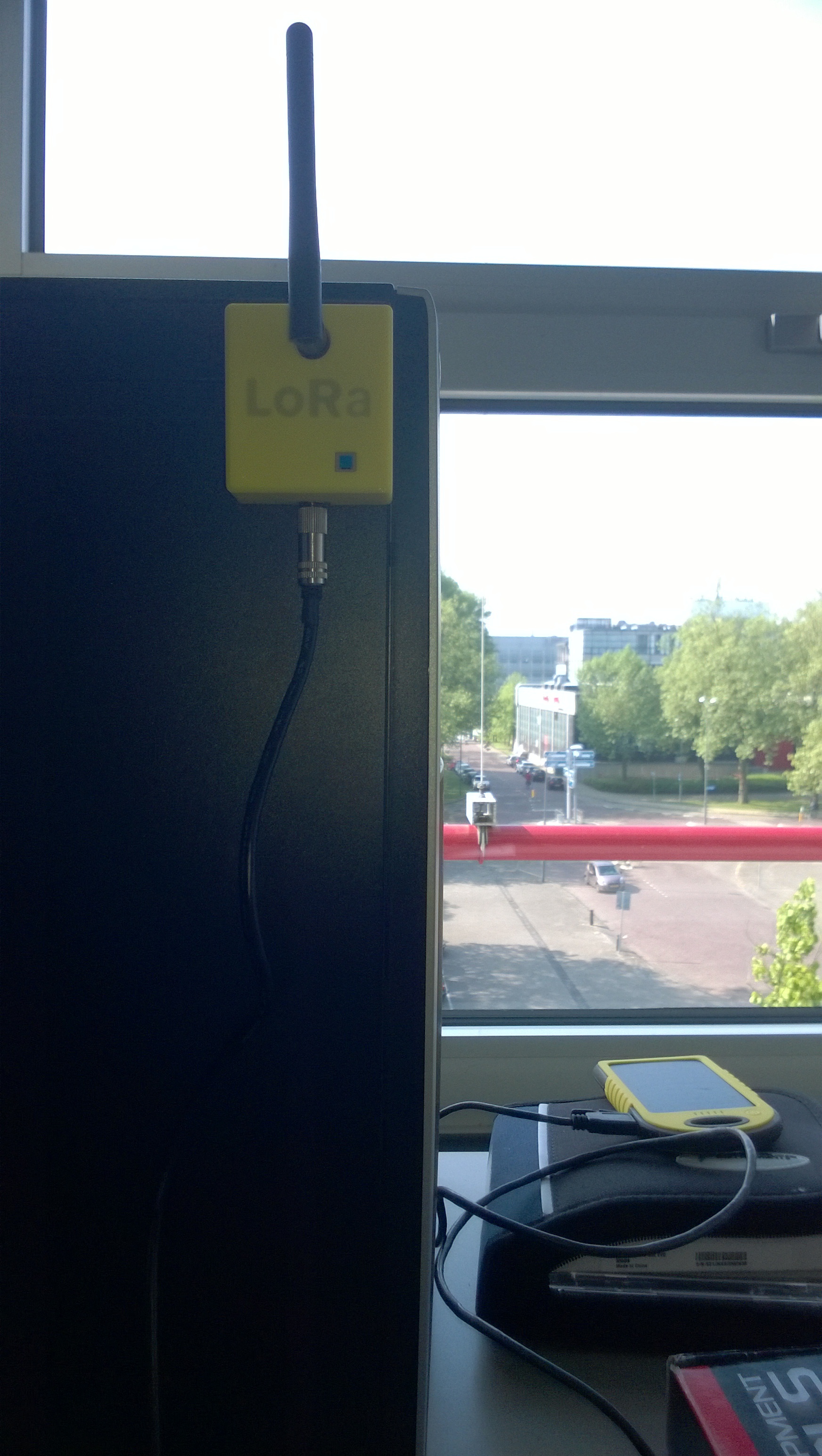
The idea for this last node is to use it as a sensor for ttnmapper.org. To power it I will use either a USB power bank, or two AA batteries.

More experiences with this type of setup can be found here on Janos’ site. He also has nice photos of his setup using an Arduino Pro Mini + RN2483 running my code.

17 Likes

The image I posted of the Arduino Nano + RN2483 combination is the cheapest TTN node I know of. In total it is around €20. The most expensive part is the RN2483, costing around €13-15. The Arduino Nano can be obtained for single digit euros (<€5) from Chinese suppliers, and the PC board was less than €2 each from http://dirtypcbs.com/.

Please let me know if you know of a way to make an even cheaper TTN node. This is unfortunately one of the biggest problems I see for large scale adoption. If we can get a device to be in the order of <€5, I see people buying them to do all sorts of small tasks. Imagine a live temperature heatmap of a city, or a soil moisture map of every square meter on a farm.

6 Likes

Great topic!

About the possibly cheapest node see this thread Not < $5 but < $10 seems possible at the moment.

1 Like

The SX1276 is available for 6$ on DigiKey so that should be a more economical option, right? I bought full modules (MCU + SX1272) for 11 euro’s from Embit. Just doesn’t have the nice Arduino headers and you need a JTAG, but other than it works fine.

Thanks for sharing this information and for this great topic @jpmeijers!

great topic!

Yes, absolutely fantastic! Thank you jpmeijers!

This is my node running TXfastViaTTN.ino on a Arduino Pro mini and a Microchip RN2483, powered by a 9V battery.

Thanks for sharing!

12 Likes

Nice Marco,

I ordered the holiday cards !

1 Like

:joy::joy:

I got it working! Unfortunately some soldering errors on the Arduino Nano made it smoke, but luckely the RN2383 was not damaged. After some ‘correctional’ wiring it started to send out the test packets, received by my Gateway and send to the TTN network.

Node:

Gateway:

TTN MQTT Packets:

Thanks @jpmeijers for the help today!

5 Likes

Good to see you got everything working. Hope to see your gateway online soon.

1 Like

For those of you who want to replicate the board we built in Enschede on Saturday (last two photos in my first post), you can get all the components at the following locations.

2 Likes

Plenty available at microchipdirect.

3 Likes

To find stuff, findchips.com is your friend: http://www.findchips.com/search/rn2483 :wink:

1 Like

Little yelow box, another node ready for driving :grinning:

6 Likes

As I have already destroyed two RN2483s with my terrible soldering skills (molten the connector of the antenna connection from the RN2483) and still have no working node, it’s time to ask for help from the experts:

I think i have connected the wires properly to the arduino and the RN2483 and uploaded the last version of the code. The blinking on the arduino is however not (as described) ‘on except for 200ms every 5 seconds’. It keeps on blinking on-off-on-off.

Do you have any idea what this could be?
Does it matter to which ‘GND’ on the Nano I connect the GND from the 2483?
There is an additional wire on pin 12 in the first picture of JPMeijers, which is not mentioned anywhere. Should I connect that one as well?

1 Like

If you mean pin 12 of the RN2483 module, it is not necessary for prototyping. It is just another 3.3V connection. All the 3.3V and all the GND pins are connected internally on the module.

On an Arduino a constant quick flashing normally means the Arduino is stuck in its bootloader. Try programming the Arduino again or pressing reset. Similar to this: bootloader - Arduino Nano not responding with yellow led blinking fast - Arduino Stack Exchange

How does your Arduino respond to other sketches? And when you program the code from my github repository, what do you see on the serial monitor?

Edit: You might also find it useful to use the Arduino example code for software serial. Change it to run at 57600 baud on pins 10 and 11, and see if you can communicate with the RN2483 from the serial monitor on your computer.

1 Like

Yes I meant pin 12 on the RN2483. So not necessary to connect to the 3V3 from the arduino as well.

When I upload the ‘blink’ example, it works as it should. I have built two of the Arduino RN2483 combinations now and both have the same problem. So perhaps it is my wiring?

Connected as follows.
Arduino nano RN2483
D10 PIN 6
D11 PIN 7
D12 Pin 32
GND GND
3V3 VDD

And some pictures to illustrate.

Will try the serial communication that you mention later today !
Do I have to connect anything to pins 10 and 11 when I do it according to your edit?

Probably some too basic questions in here indicating that I should read some manuals first :slight_smile:
postimg.org/image/kqvikwrmz/
postimg.org/image/8rk0dlm23/
postimg.org/image/fkkd9vcvf/
postimg.org/image/4twqo6z8r/

EDIT:

I am now getting the following feedback through the serial monitor. This means that communication between Arduino and RN2483 is working, correct?

The registration of my application I have done through “https://staging.thethingsnetwork.org/” instead of the ttnctl app. It was mentioned that I have to add the parameter “–relax-fcnt”. Is this required for receiving packages? I am not sure where I could add it in the mentioned website.

Will drive around today with my node and then see if I can receive some messages on the website.
Thanks again for helping out!

Startup
When using OTAA, register this DevEUI:
0004A30B001B4219
RN2483 version number:
RN2483 1.0.1 Dec 15 2015 09:38:09
TXing
TXing
TXing

1 Like

When I turn on the serial monitor with the original code, I get the following, (where ÿ means -1, meaning something isn’t correct I think.

ðÿñþüÿÿü�ÿâýýÿÿÿÿÿ
Ñþÿþþÿÿÿÿÿüýÿÿÿþÿüýÿÿÿÿÿÿüÿÿÿÿÿÿÿÿÿÿÿÿüýüÿþÿÿÿÿÿÿÿþÿüÿÿüÿÿþÿüýÿÿÿÿÿÿÿÿÿüýüÿþÿþÿÿÿÿÿþÿþÿþÿþÿüÿÿÿüýüÿÿÿÿüÿÿÿÿüÿüÿÿ

When I run the SoftwareSerial example (https://www.arduino.cc/en/Tutorial/SoftwareSerialExample) (only USB plugged into the arduino and the RN2483 connected as it was), I do not get the ‘Goodnight moon’ message that I would expect (looking at the example code).

This indicates something isn’t good, or am I misinterpreting the functioning of the serial monitor?

EDIT 13-06:

I am now getting the following feedback through the serial monitor (by changing the baud rate in the serial monitor). This means that communication between Arduino and RN2483 is working, correct?

Startup
When using OTAA, register this DevEUI:
0004A30B001B4219
RN2483 version number:
RN2483 1.0.1 Dec 15 2015 09:38:09
TXing
TXing

The registration of my application I have done through “https://staging.thethingsnetwork.org/” instead of the ttnctl app. It was mentioned that I have to add the parameter “–relax-fcnt”. Is this required for receiving packages? I am not sure where I could add it in the mentioned website.

Will drive around today with my node and then see if I can receive some messages on the website.
Thanks again for helping out!

Edit 14-06:
Drove around the Hague and Amsterdam with my node on, but no messages in my TTN Dashboard yet unfortunately. Any ideas?