Aha! I want to know what hardware your using for the hive 16Km from the GW!
lol…
Aha! I want to know what hardware your using for the hive 16Km from the GW!
lol…
Absolutely ![]() Theoretical ‘piece of string’ questions can be a guide…but its what works in the real world that counts…and can only be found by testing!
Theoretical ‘piece of string’ questions can be a guide…but its what works in the real world that counts…and can only be found by testing! ![]()
Longest beehive connection I have is just over 9km with SF8 - not to my (clients) GW (which services the hive just fine anyhow from ~1.2km away) but to another community unit other side of valley downstream…
Fact is, as with the 70km range response earlier, we know these longer ranges are possible… 'cause LoRa Yay! but when planning for a deployment is it dangerous to assume possible and plan for shorter… then be pleaseantly suprised by what the real world delivers for us ![]()
![]()
![]() Just dont want to set wrong expectations for @rcooke…
Just dont want to set wrong expectations for @rcooke…
WIth the ant poking through a hole in the top? If so likley the lid acts as a very efficient ground plane assisting enable great range! ![]()
Damn - too late!
Key is look at the pictures - great altitute for the link, no ground clutter and reasonably clean freznel zone! (Ok some detraction but usable)… in your case you have chuffing great ridges in the way that makes what ever materials used and construction/form somewhat moot! ![]()
And from Johan’s description definetly not likely to be a Laird RS1xx - and so off topic ![]() as is much of this discussion and will now likely need moving to a clean/new thread…
as is much of this discussion and will now likely need moving to a clean/new thread…
The antenna is in the hive, I think the RF bounces off the lid and then of the ground, then to the gateway.
Actually there are no LOS, slight rise in the hill by the node and 30m of trees in the LOS
Here is one more hive 6.7km at SF 10
I have 7 hives with the same setup, bar 2 all all at SF7 and greater than 6Km
Don’t expect a lot, you need to test and then deploy.
Sorry off topic posting about bees. ![]()
So this would be?
You do appear to have enough knowledge to determine if you will violate the limits.
Yes, and I said “LoS to where? There are tools to check actual LoS but it needs the other end …”. No point pointing out that you gave the Lat/Long if the actual point I was pointing out is that you have only given ONE Lat/Long.
Device = node = sensor+radio. Gateway = gateway. Very few COTS gateways come with mast antenna, you choose the antenna, so you are going to need to know about its gain plus losses in the cabling.
Which will most likely breach FUP so you’ll need to keep the uplink interval to about two per hour, depending on payload format.
Feel free to carry on learning LoRaWAN by blunt force trauma, but be aware that enthusiasm for supporting those that employ this technique wanes pretty quickly.
Pretty much the same as everyone else - if you go and count the number of manufacturers of LoRa chipsets - so it will be down to the antenna but I feel we’re going to be rinsing and repeating …
What about SWR, G?
Next you’ll want to talk about radiation patterns which will set @Jeff-UK off on too good an antenna creating a dead patch in the immediate area, or some such.
I have always found it interesting that when someone is say giving a learned lecture on antennas, and they put up all those fancy pictures and diagrams with weird names and that look like the ring dounuts you get from the supermarket, there is most often no practical evidence of range testing and how the antenna actully performs in the real world.

@LoRaTracker Do worry I have 100% no idea where my nodes are, nor to which gateway they work to, the RSSI, SF, SNR, consume airtime, battery life and I just uplink every 6s and down every 30s.
So I must be 100% compliant.
What would be the way to test an antenna:
I’ve got plenty of results from nodes and gateways in the field, however there are too many variables I don’t control and that aren’t visible in those results (parked cars or other shielding objects, weather conditions among them). For an objective test how an antenna performs these need to be excluded so all antennas will be tested under the same conditions. That is hard without a fully equipped lab and Anechoic Chamber, isn’t it?
And multiple copies of each - which makes for a bit of a headache - and then there is long term degradation of the materials so it needs to be for a while.
Maybe a quick sequence of tests in a open field over the space of a few hours to categorise them is the most realistic we can get - I think I’ve seen pictures of Stuart’s setup in a field somewhere here or on his blog.
Its actually very easy to do real World comparisions of antennas, you do need some LoRa nodes, one as a transmitter and another as a receiver.
No need for an Anechoic Chamber either, your not going to put the Gateway in an anechoic chamber so why test it in one. All you need is a large open field, a transmitter and receiver and some long bamboo poles, oh and its helpful if you have built a 1/4wave vertical with radials antenna as reference.
In simple terms you mount the transmitter, which sends out test packets, on a large bamboo pole, say 2M off the ground, or more if you want. Then with the referance antenna in place go 50m or 100m away and measure the RSSI of the received packets, the antenna on the receiver does not matter as long as you use the same one for each comparison. Put the receiver on a pole too so you can stand out of the way. A display on the receiver helps, or you can just use a long serial lead and laptop to read the receiver output.
Swap antennas and do the measurement again. You now know the real world performance differance, in dBm, between the two antennas. And your measuring what you want to know, the performance at roughly horizontal, outdoors, in the real world. Want to put the test transmitter on top a roof, then do so, go a long distance away, read the signal RSSI, swap antennas and repeat.
Some descriptions of past testing endevours are described here;
The link testing software, including the decending power level stuff is in my library.
If you use the same large open field, referance antennas, heights of antennas, software etc, you can go back a year later and run the same tests so you can compare the performance of a new antenna.
There was once an antenna design touted as an easy to build good gain job. It was designed by ‘someone’ who has given talks on propagation at TTN conferances. The antenna was indeed fairly easy to build, just bits of wire some straight and some coiled. The SWR match was very low indeed, so must be a real good antenna ? So over to my local playing field I went, and compared it to my 1/4wave vertical with radials. This easy build antenna was rubbish, somewhere around 4-6dBm down on the much smaller 2dBi referance. Why such a poor real world antenna, no idea, maybe it was radiating up at the heavens.
And if you reduce the power output of the transmitter enough, put it in a tin or wrap it in foil, you can use a receiver, with a beeper fitted, that you fit with the antenna to test and walk away until the receiver stops beeping. The distance comparison between antennas gives you the relative gains. The technique is describe for 2.4Ghz antennas here.
https://stuartsprojects.github.io/2019/04/27/Antennas-for-SX1280-2-4Ghz-LoRa-tranceivers.html
In that test it literally took 10 minutes to do a real worl comparison between 6 antennas.
There is more examples of using ‘ping’ testing for antenna\receiver comparisons here;
Yep large open field.
If you go to a garden centre you will find quite long bamboo poles, tie 3 together at the end, and you can quickly form a stable tripod, which you can then hang antennas from with string.
Wrap the transmitter and battery together with PVC tape and hang from the antenna plug with SMA connectors etc.
Somewhere I’ve one of DaveA’s but as I moved early 2020, I’m not sure where it’s gone. It was the classic SMA / Guitar String soldered combo, finding info on lengths is simple enough (like 1/4 Wave Ground Plane Antenna Calculator – M0UKD – Amateur Radio Blog)
But do you have a recommended set of instructions for an own build or is the SMA Guitar acceptable?
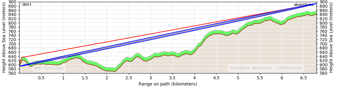
I cannot find my 868Mhz one either, but here are pictures of my 434Mhz one, build is the same, just use different wire lengths.
Using Guitar wire is OK for HABs, light weight etc, but the ends are very pointy and it can be difficult to solder. Simple copper wire extracted from a bit of (not live!) mains cable is easier to build with, and you can use solder tags to attach rather than crimp. And if you want to pack it away, uncrew the solder tags.
That antenna is quite difficult to get wrong, so Joe in Australia should get the same performance in a large field as Fred in the UK, so global antenna comparisons should be valid.
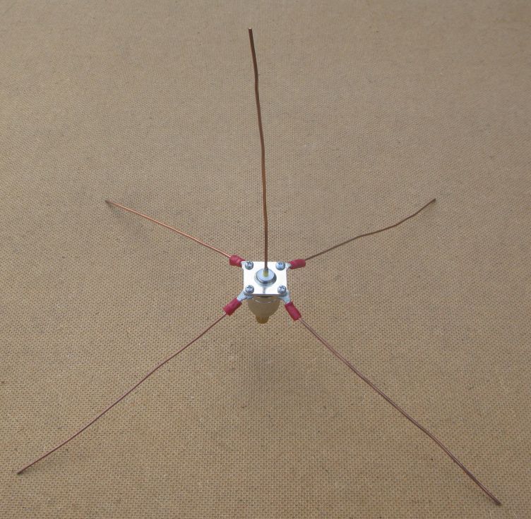
Its so easy to build, you dont really need instructions. Its uses an N-Type chassis socket.
Genius!
Use the conductor strands for 10mm2 house wire, you going the need about 30cm of it and appropriate SMA connector.
2 Solder the two onto SMA connector.
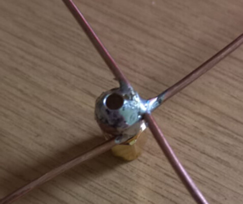
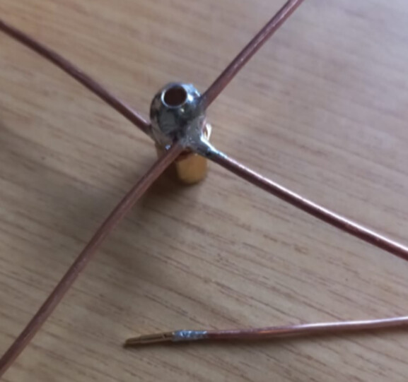
Fit some heat shrink around the conductor.
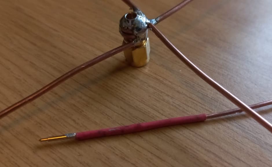
Fit the center conductor to the SMA connector and ensure the pin is all the way home. Now add some epoxy to keep it in place.
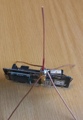
Fit to node and test, you will need to trim for optimum performance.
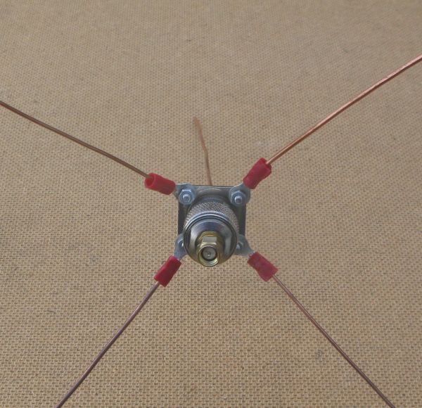
As you have the crossover mounted to the side of the SMA it is likely unbalanced wrt polar plot and with slightly deminished SWR…unless you have tuned and balanced each arm. Best is get the crossover point over the hole and take the vertical up from there… also IIRC the ‘arms’ create a virtual ground plane for the vertical and having it mounted directly over the pcb/components will further unbalance and detune. Best is use a short stub cable - say 4-8cm long to another sma connector to mount to the pcb sma - that will lift the arms clear and improve performance (Again IIRC - I need to go check old designs from a few years back ![]() )
)