I have always found it interesting that when someone is say giving a learned lecture on antennas, and they put up all those fancy pictures and diagrams with weird names and that look like the ring dounuts you get from the supermarket, there is most often no practical evidence of range testing and how the antenna actully performs in the real world.
2 Likes

1 Like
@LoRaTracker Do worry I have 100% no idea where my nodes are, nor to which gateway they work to, the RSSI, SF, SNR, consume airtime, battery life and I just uplink every 6s and down every 30s.
So I must be 100% compliant.
What would be the way to test an antenna:
- without breaking the bank.
- requiring many miles of LOS visibility
- that produces usable, objective, results
- with a manageable amount of effort
I’ve got plenty of results from nodes and gateways in the field, however there are too many variables I don’t control and that aren’t visible in those results (parked cars or other shielding objects, weather conditions among them). For an objective test how an antenna performs these need to be excluded so all antennas will be tested under the same conditions. That is hard without a fully equipped lab and Anechoic Chamber, isn’t it?
And multiple copies of each - which makes for a bit of a headache - and then there is long term degradation of the materials so it needs to be for a while.
Maybe a quick sequence of tests in a open field over the space of a few hours to categorise them is the most realistic we can get - I think I’ve seen pictures of Stuart’s setup in a field somewhere here or on his blog.
Its actually very easy to do real World comparisions of antennas, you do need some LoRa nodes, one as a transmitter and another as a receiver.
No need for an Anechoic Chamber either, your not going to put the Gateway in an anechoic chamber so why test it in one. All you need is a large open field, a transmitter and receiver and some long bamboo poles, oh and its helpful if you have built a 1/4wave vertical with radials antenna as reference.
In simple terms you mount the transmitter, which sends out test packets, on a large bamboo pole, say 2M off the ground, or more if you want. Then with the referance antenna in place go 50m or 100m away and measure the RSSI of the received packets, the antenna on the receiver does not matter as long as you use the same one for each comparison. Put the receiver on a pole too so you can stand out of the way. A display on the receiver helps, or you can just use a long serial lead and laptop to read the receiver output.
Swap antennas and do the measurement again. You now know the real world performance differance, in dBm, between the two antennas. And your measuring what you want to know, the performance at roughly horizontal, outdoors, in the real world. Want to put the test transmitter on top a roof, then do so, go a long distance away, read the signal RSSI, swap antennas and repeat.
Some descriptions of past testing endevours are described here;
The link testing software, including the decending power level stuff is in my library.
If you use the same large open field, referance antennas, heights of antennas, software etc, you can go back a year later and run the same tests so you can compare the performance of a new antenna.
There was once an antenna design touted as an easy to build good gain job. It was designed by ‘someone’ who has given talks on propagation at TTN conferances. The antenna was indeed fairly easy to build, just bits of wire some straight and some coiled. The SWR match was very low indeed, so must be a real good antenna ? So over to my local playing field I went, and compared it to my 1/4wave vertical with radials. This easy build antenna was rubbish, somewhere around 4-6dBm down on the much smaller 2dBi referance. Why such a poor real world antenna, no idea, maybe it was radiating up at the heavens.
And if you reduce the power output of the transmitter enough, put it in a tin or wrap it in foil, you can use a receiver, with a beeper fitted, that you fit with the antenna to test and walk away until the receiver stops beeping. The distance comparison between antennas gives you the relative gains. The technique is describe for 2.4Ghz antennas here.
https://stuartsprojects.github.io/2019/04/27/Antennas-for-SX1280-2-4Ghz-LoRa-tranceivers.html
In that test it literally took 10 minutes to do a real worl comparison between 6 antennas.
There is more examples of using ‘ping’ testing for antenna\receiver comparisons here;
2 Likes
Yep large open field.
If you go to a garden centre you will find quite long bamboo poles, tie 3 together at the end, and you can quickly form a stable tripod, which you can then hang antennas from with string.
Wrap the transmitter and battery together with PVC tape and hang from the antenna plug with SMA connectors etc.
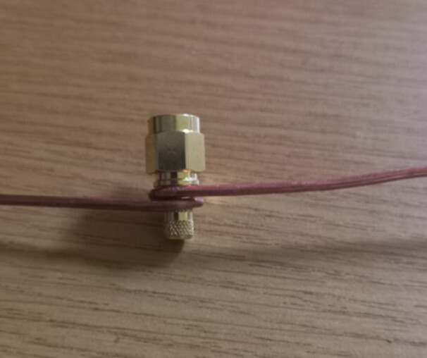
Somewhere I’ve one of DaveA’s but as I moved early 2020, I’m not sure where it’s gone. It was the classic SMA / Guitar String soldered combo, finding info on lengths is simple enough (like 1/4 Wave Ground Plane Antenna Calculator – M0UKD – Amateur Radio Blog)
But do you have a recommended set of instructions for an own build or is the SMA Guitar acceptable?
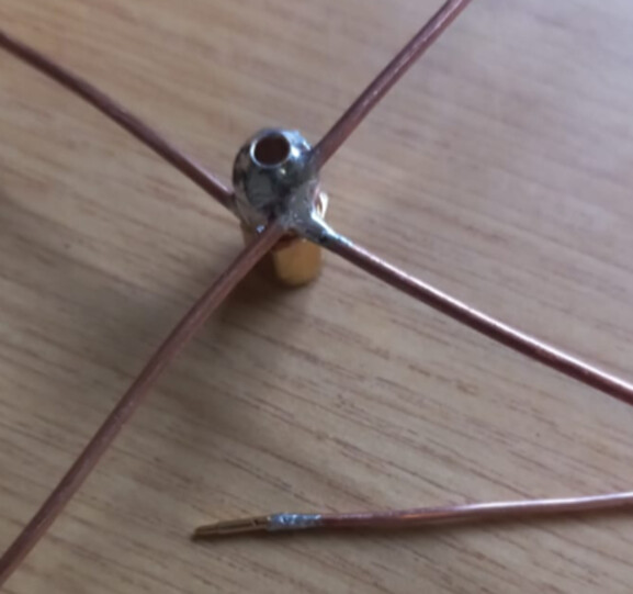
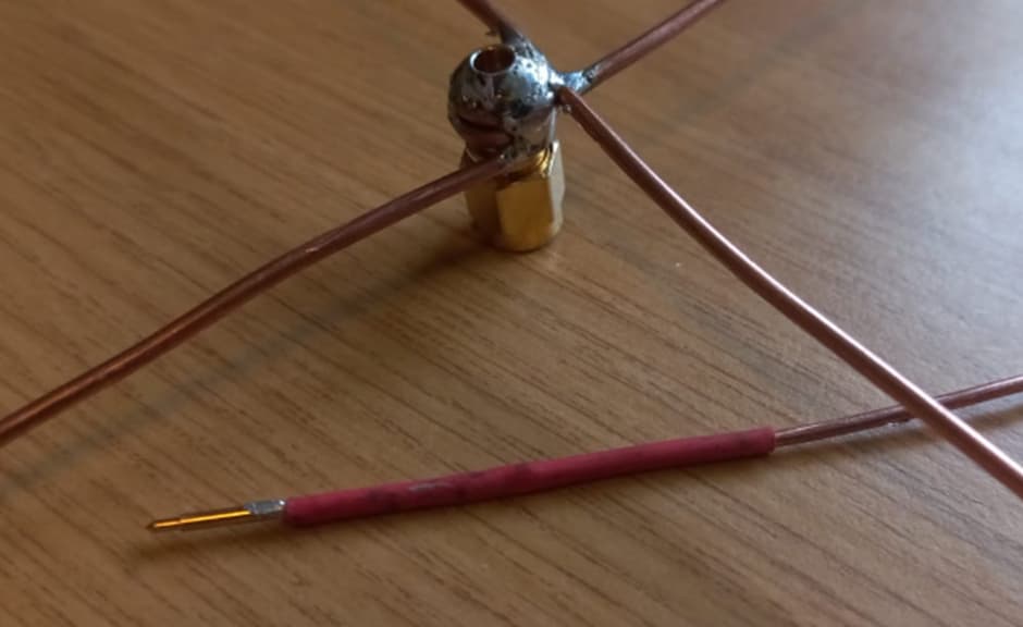
I cannot find my 868Mhz one either, but here are pictures of my 434Mhz one, build is the same, just use different wire lengths.
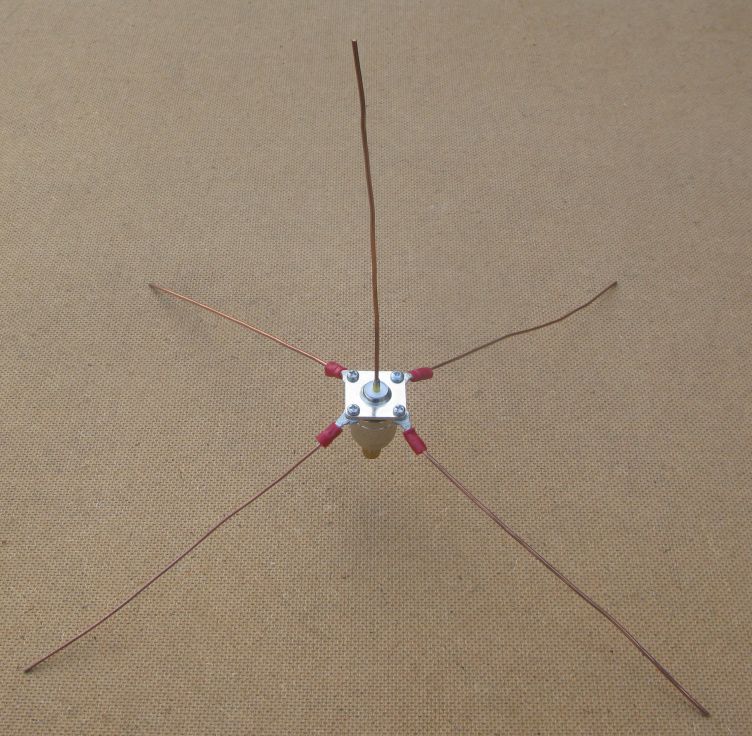
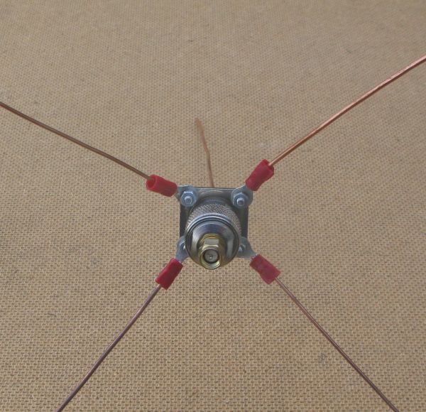
Using Guitar wire is OK for HABs, light weight etc, but the ends are very pointy and it can be difficult to solder. Simple copper wire extracted from a bit of (not live!) mains cable is easier to build with, and you can use solder tags to attach rather than crimp. And if you want to pack it away, uncrew the solder tags.
That antenna is quite difficult to get wrong, so Joe in Australia should get the same performance in a large field as Fred in the UK, so global antenna comparisons should be valid.
Its so easy to build, you dont really need instructions. Its uses an N-Type chassis socket.
Genius!
Use the conductor strands for 10mm2 house wire, you going the need about 30cm of it and appropriate SMA connector.
- Bend the center point of wire around a drill bit of appropriate diameter and then fit onto SMA connector. Make 2 of these.
2 Solder the two onto SMA connector.
- Solder center pin of SMA connector onto +/-10cm of a piece of the strands from the 10mm house wire. (868MHz +- 8.2cm and 915Mhz +/-7.7cm)
-
Fit some heat shrink around the conductor.
-
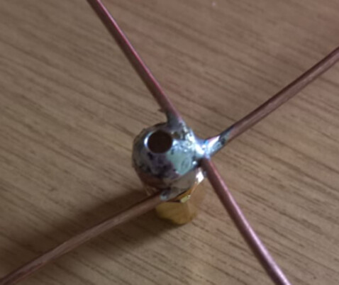
Fit the center conductor to the SMA connector and ensure the pin is all the way home. Now add some epoxy to keep it in place.
-
Fit to node and test, you will need to trim for optimum performance.
2 Likes
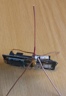
As you have the crossover mounted to the side of the SMA it is likely unbalanced wrt polar plot and with slightly deminished SWR…unless you have tuned and balanced each arm. Best is get the crossover point over the hole and take the vertical up from there… also IIRC the ‘arms’ create a virtual ground plane for the vertical and having it mounted directly over the pcb/components will further unbalance and detune. Best is use a short stub cable - say 4-8cm long to another sma connector to mount to the pcb sma - that will lift the arms clear and improve performance (Again IIRC - I need to go check old designs from a few years back ![]() )
)
A convenient build technique that could potentially be tweaked by having the radials bent around the SMA connector so they come out centred.
As a reference antenna I guess it’s not ideal but it’s still a reference.
Indeed, the point of using a simple referance antenna, is that its just that; a reference and simple to make. Its useful if the reference used is the same the World over, but its absolute performance to fractions of a dBm does not really matter.
If you comparing a series of antennas, A, B, C and you just want to know which is the best, then you dont really need a reference in the first place.
If you attempt to idealise the construction, using co-ax cables and the consequent ferrite rings as chokes etc, you just turn something simple into something not simple, types of co-ax, lengths, types of ferrite rings etc.
An additional benefit of a standard (and simple!) reference is that you can come up with a reference performance standard that allows you to know, without using absurdly compex equipment, if the LoRa devices are actually working correctly. If using the standard easy build reference antennas with them say 2M off the ground, and transmitting at say, 14dBm and 50m away I get an RSSI of -60dBm in the UK, Franz in Germany has a problem with one of their devices if they only get -70dBm.
+1 for that! Lol. Indeed. and since this is Canada, I’m going to have a nice snow-load shortly… The fluffy stuff always does “interesting” things to radio waves!
Me prioritizing my concerns. The full statement should be:
- I do not care about that issue, yet.
- After I exhaust my test options with the hardware I have on hand, I hope to have learned enough to formulate what to do next.
Does anybody have experience with the iOS app for Laird?
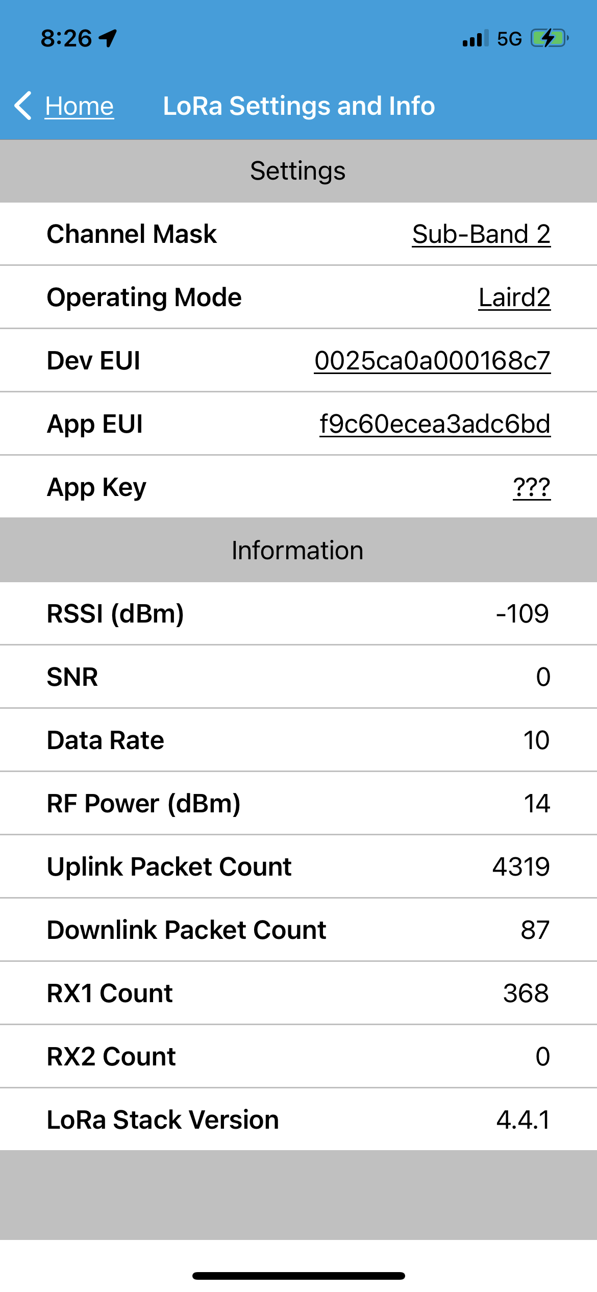
I took the sensors home (7Km away) again. I wanted them to roll back to lowest data rate so I could do a range test Monday morning on the way to work.
The LHT65 seemed to go offline. The Laird seems to be talking to a Gateway, but not mine!
The pic is the LoRa status in the iOS app.
How do I tell from that, or any other screen, if the LAIRD is able to connect to a gateway? And, since that gateway likely will not be forwarding to the cloud I’m on, I assume it wont get a reply?
Or maybe more generally, is there a way to tell the LAIRD sensor is getting replies from a gateway?
What do you see in the Console - Application - Live Data?
What do you see in the Console - Gateway - Live Data? (your gateway)
What is your gateway ID, is it on line all the time?
If you look in Console - Application - Live Data and you expand the uplink message you will see all the metadata, including information about the gateways you are using to connect to the NS.
1 Like
All gateways (TTN), does matter if it your or not, will forward the uplink to your application.
LoRaWAN devices connect to a network server, not to a gateway. LoRaWAN is not WiFi.
Any TTN connected gateway in range of the RF transmission will forward the data to TTN.
1 Like