Library Error Message

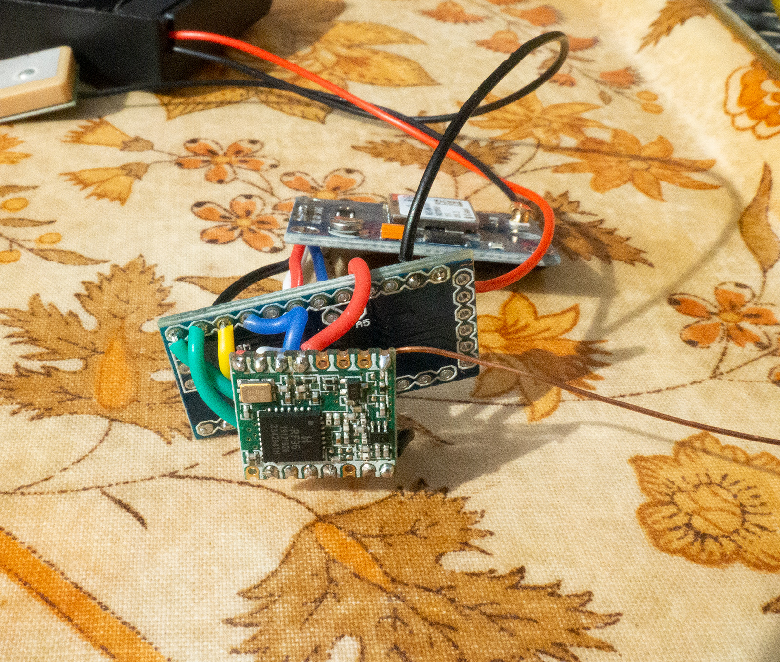
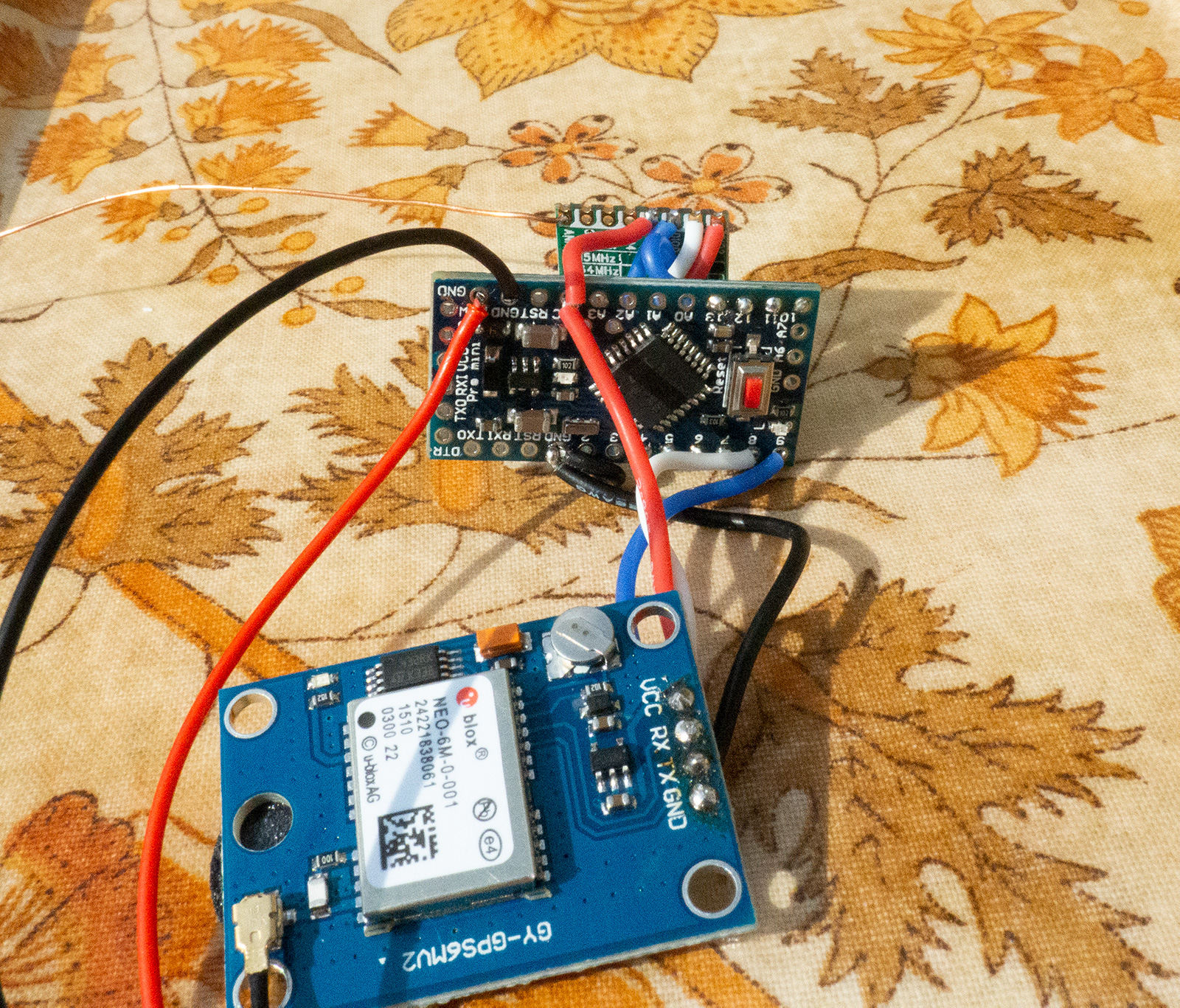
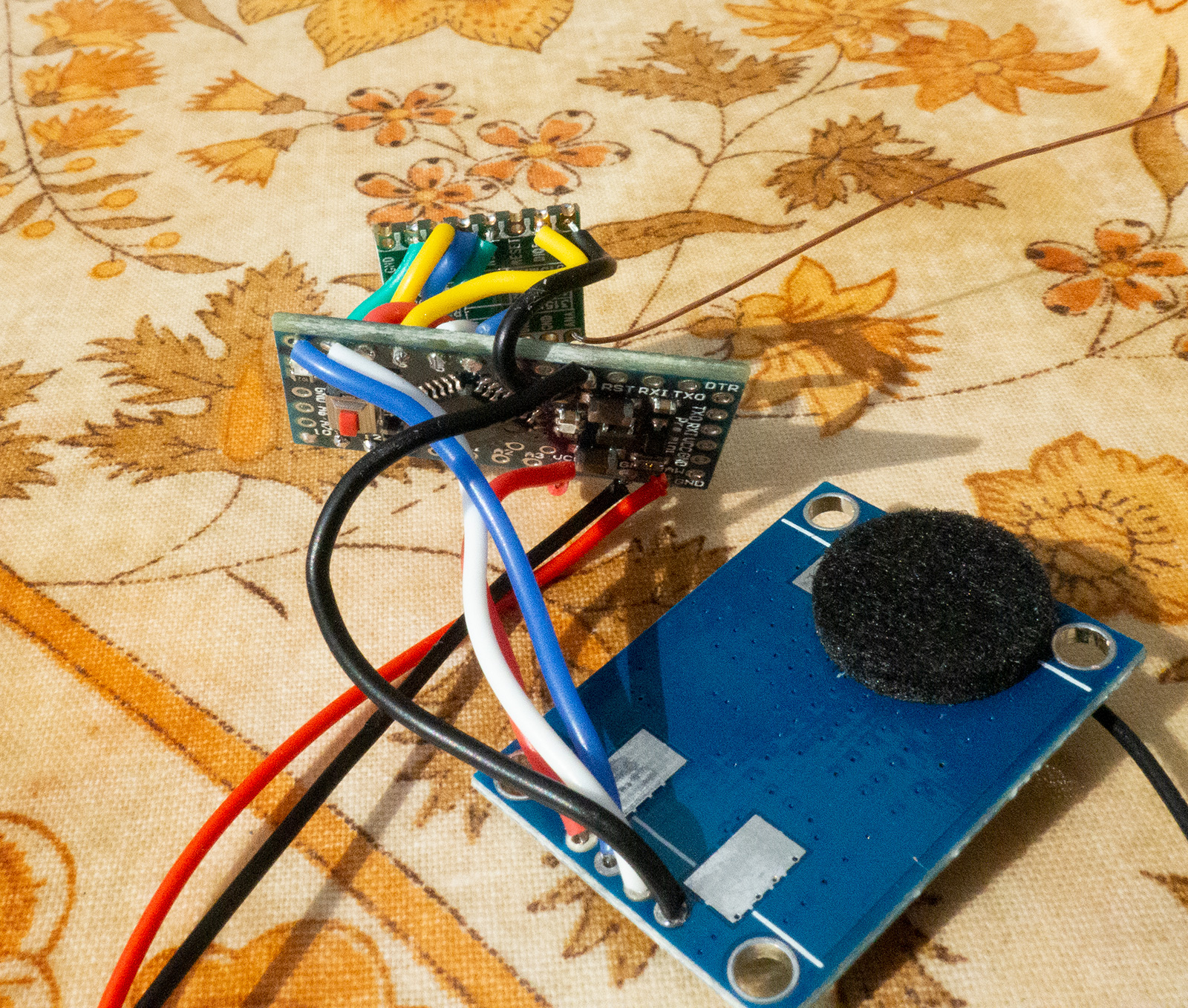
I’ve built a small Arduino tracker using the design found here: https://www.thethingsnetwork.org/labs/story/lorawan-gsp-tracker

Following advice from someone who has built something similar I’ve compiled it using the IDE version 1.8.9 and the LMIC library 2.2.2 which together leave a reasonable amount of memory free. Using the latest versions left just 55 bytes.

The problem is when I try to run it this is what appears in the Serial Console:

Starting

FAILURE
C:\Users\rjohn\Documents\Arduino\libraries\MCCI_LoRaWAN_LMIC_library-2.2.2\src\lmic\oslmic.c:53

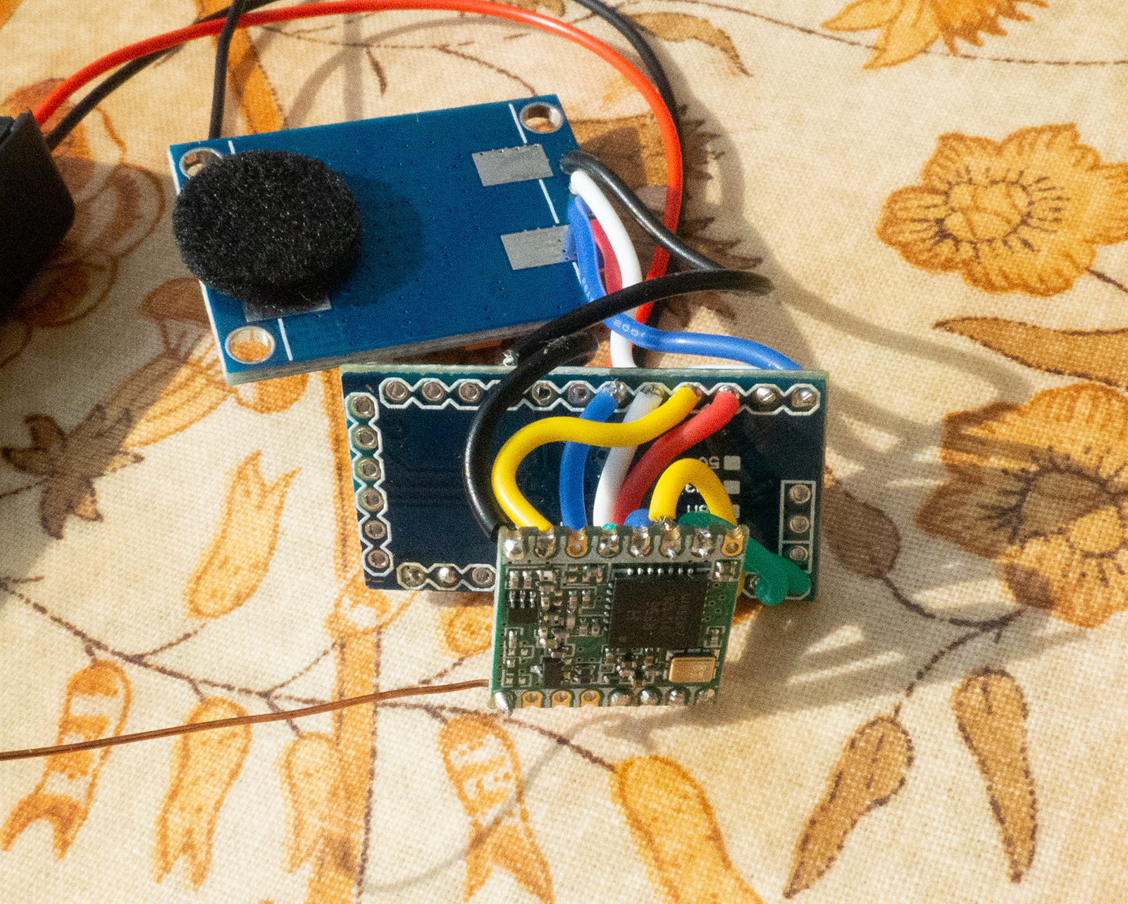
I got exactly the same message using the latest version of the LMIC library. Version 2.2.2. is the only one on my PC now. I’ve double checked the pin mapping and the physical wiring and can’t find anything wrong.

Any suggestions on how to resolve this would be most welcome.

This typically results from a failure of the radio in it routine which is typically a failure to read the expected ID code for the compiled chip configuration, as attempted here:

Typically the cause is either:

  1. SPI wiring problems
  2. Building the code for sx1276 while having sx1272, or the reverse.

Consider putting some serial.println() debugging in that part of the radio code, and check your wiring.

After you get it working take the debug changes back out… git diff is great for finding them.

1 Like

That would be me, I’ve a few hundred going but mostly built by the wife.

John, can you post a picture of the radio chip you are using please

1 Like

Here are a few photos I’ve just taken. I did swap over the MISO and MOSI wires from the original build as I found conflicting pinout diagrams for the board. I’m currently using D11 for MISO and D12 for MOSI but it didn’t work the other way round either. I may have broken something in the process of course. I have checked with a multimeter all the connections and examined each joint under a strong magnifying glass having been caught out by stray “whiskers” in the past. I’ve just noticed there are some whiskers on the yellow wire going to the MOSI pin on the LoRa module but they are short and aren’t touching anything. I may have to dismantle the whole thing and start again to be absolutely sure about the joints.

T1
T2
T3
T4
T5

D12 is MISO and D11 is MOSI.

Fix that, then add a debug print around line 1111 of radio.c

u1_t v = readReg(RegVersion);
Serial.print("Radio identity register reads: ");
Serial.println(v, HEX); //or whatever the arduino syntax is 
#ifdef CFG_sx1276_radio

Likely you’ll get 0, 0xFF or one of the expected values 0x12 or 0x22, and which you get will be a key clue to the problem.

SORRY, NO, THIS WON’T WORK. radio.c is C code and has no awareness of Arduino C++ objects and their methods. You’d have to examine the code and find what other mechanism LMiC is using for debug output on your platform.

1 Like

Thank you for that, I wish the pin diagrams were consistent! I’ll get the soldering iron out. :slight_smile:

The newer versions of that library are too large for the ATMega328P, in combination with a compiler update from Arduino IDE 1.8.10, you end up with larger than flash and no memory left. So John is using 2.2.2 which makes the line number:

Higher powers advised me that unless I wanted to run CAD or some other parts, that only DI0 and DI1 were required beyond the SPI & power. Does make it easier to wire up, but these are a useful way of mounting RF module:

https://www.amazon.co.uk/dp/B07Y8FV9Q8/

Some minor cuts are needed to work.

Thank you! I’ve swapped the MISO/MOSI wires around (kicking myself for getting that wrong) and it is now doing something. The output form the serial console now begins like this:

Starting
$GPRMC,,V,,,,,,,,,,N*53
$GPVTG,,,,,,,,,N*30
$GPGGA,,,,,,0,00,99.99,,,,,,*48
$GPGSA,A,1,,,,,,,,,,,,,99.99,99.99,99.99*30
$GPGLL,,,,,,V,N*64
63744: Unknown event
Packet queued
324229: EV_TXCOMPLETE (includes waiting for RX windows)
$GPRMC,,V,,,,,,,,,,N*53
$GPVTG,,,,,,,,,N*30
$GPGGA,,,,,,0,00,99.99,,,,,,*48
$GPRMC,,V,,,,,,,,,,N*53
$GPVTG,,,,,,,,,N*30
$GPGGA,,,,,,0,00,99.99,,,,,,*48
$GPGSA,A,1,,,,,,,,,,,,,99.99,99.99,99.99*30

The GPS can’t get a fix indoors so I’ll try it on batteries outside and see if it is transmitting anything using an SDR.

It didn’t work when wired this way originally but that may have been because of the low (55 byte) memory.

Woo Hoo!

1 Like

I may have spoken too soon. I have managed to get the GPS to see a bit of sky and it has a fix. Running the serial console now gives something more helpful but I can’t see anything on the SDR waterfall.

Starting
,162121.00,5022.46851,N,00401.53977,W,1,04,8.45,79.1,M,50.3,M,,*7C
$GPGSA,A,3,06,19,17,02,,,,,,,,,9.49,8.45,4.32*00
$GPGSV,3,1,09,02,20,311,26,03,38,084,,04,70,091,,06,58,296,23*7D
$GPGSV,3,2,09,07,02,167,,09,59,199,14,17,29,223,09,19,38,243,20*76
$GPGSV,3,3,09,22,18,092,*42
$GPGLL,5022.46851,N,00401.53977,W,162121.00,A,A*7D
$GPRMC,162122.00,A,5022.46832,N,00401.53991,W,0.066,,130820,,,A*62
$GPVTG,,T,,M,0.066,N,0.123,K,A*23
$GPGGA,162163843: Unknown event
Packet queued
353385: EV_TXCOMPLETE (includes waiting for RX windows)
22.00,5022.468Ɋ	⸮⸮⸮⸮r⸮⸮⸮ʊb⸮⸮1,04,8.45,79.1,M,50.3,M,,*72
$GPGSA,A,3,06,19,1$GPRMC,162147.00,A,5022.47721,N,00401.62552,W,2.682,,130820,,,A*62
$GPVTG,,T,,M,2.682,N,4.968,K,A*2E
$GPGGA,162147.00,5022.47721,N,00401.62552,W,1,05,2.06,104.4,M,50.3,M,,*4E
$GPGSA,A,3,04,06,19,17,02,,,,,,,,3.77,2.06,3.16*0F
$GPGSV,3,1,10,02,20,311,26,03,37,084,,04,70,090,07,06,58,296,26*79
$GPGSV,3,2,10,07,02,167,,09,59,199,07,17,28,223,08,19,38,243,20*7C
$GPGSV,3,3,10,22,18,092,,31,08,027,*75
$GPGLL,5022.47721,N,00401.62552,W,162147.00,A,A*7D
1666830: Unknown event
Packet queued
1877099: EV_TXCOMPLETE (includes waiting for RX windows)

I’m struggling to get this to work. I’ve added your suggested lines (at the 765 line area Nick identified) but it comes back on attempting to compile that “Serial” is undeclared.

Some points that may be of interest;

Some SDRs might miss a short TTN packet, then can be sometimes difficult to see at SF7, a lot easier to see at SF12.

If you suspect a wiring issue or dead module issue, I do have standalone Arduino programs, no library install needed, that will print out the registers of the device, its a visual check that the device is at least responding. Versions for SX127x, SX126x.

1 Like

I have a single channel TTN gateway which I have had running as well and that hasn’t picked anything up even over a long period of listening. I even tried setting every channel to the frequency it uses but without success.

If you have a program I could use to test out the radio that would be very helpful.

@LoRaTracker

Well it does not test out the radio in the sense thats working as a receiver or transmitter, but it does tell you if the module is accessible over the SPI bus. Its normally the first program I use when testing a new board or setup.

I dont recall a case where a LoRa device was accessible register wise, but did not work as a transmitter or receiver. The exception is that using a LoRa module with no antenna connected can damage its TX output and it goes very low output, but still works.

For an SX127X goto here;

https://github.com/StuartsProjects/SX12XX-LoRa

And browse to;

\examples\SX127x_examples\basics\2_Register_Test

But do appreciate that I cannot be sure that this program would work on a so called ‘single channel TTN gateway’ and these devices are not supported by the forum and should not be used for TTN.

2 Likes

There is no such thing as a single channel gateway. LoRaWAN gateways receive on multiple channels and spreading factors.

That might well happen if the frequency and spreading factor do not match.

You specified the right spreading factor as well?

If you need to debug a node having access to a LoRaWAN gateway (a specifications compliant one) helps. Debugging with known limited hardware results in two challenges.

1 Like

The register test seems to have worked. This is the start of the output and it is returning 0x12

2_Register_Test Starting
LoRa Device found
Device version 0x12
Frequency at Start 434199936
Registers at Start
Reg 0 1 2 3 4 5 6 7 8 9 A B C D E F
0x00 00 88 1A 0B 00 52 6C 8C CC 8F 08 2B 01 49 00 00
0x10 00 FF 00 00 00 00 00 00 00 00 00 00 00 92 70 05
0x20 00 08 18 40 00 00 04 00 00 00 00 00 00 50 14 40
0x30 00 C3 05 67 1C 0A 03 0A 42 34 40 1D 00 A1 00 00
0x40 C0 00 12 24 2D 00 03 00 04 23 00 09 05 84 32 2B
0x50 14 00 00 10 00 00 00 0F E0 00 0C 00 06 00 5C 78
0x60 00 19 0C 4B CC 0D C1 20 04 47 AF 3F A7 00 15 0B
0x70 D0 01 13 00 00 00 00 00 00 00 00 00 00 00 00 00

Yes, it isn’t a proper gateway, just a single channel Raspberry Pi thing. The program was configured to listen on SF12 but I’ve just tried it on SF7 but no change in the result. I need to look at the tracker program again and see what it is using.

I suspect I’m going to have to put this all on hold until I’ve got a proper gateway. The price of the indoor ones has come down a lot in price. :slight_smile:

Edit:. I’ve just ordered a £75 indoor gateway from RS. It should arrive tomorrow.
To be continued…

2 Likes

I’d travel hopeful on this. The LMIC isn’t falling over due to lack of response from the RF96, so it may simply be that it’s transmitting in a way your, ahem, Pi thing of which we do not mention, can’t hear. I’ve been pretty harsh with some soldering jobs and have yet to kill a module, so I’d be surprised if you’ve broken yours.

Which code base are you using? Are you ABP or OTAA? If you let me know I can setup a test rig.

The LMIC library needs a little setup love to enable debug printing which is implemented via printf, the details of which I can dig out in the morning but I don’t think debugging at that level is going to be necessary.

1 Like

Sorry, my oversight! radio.c is of course C code which knows nothing about Arduino C++ class objects.

If you still need this, try looking through the LMIC code to see what mechanism it does use to generate some of the debug output you quoted.

Though from your subsequent posts it sounds like you’ve moved beyond a complete SPI failure.

1 Like