Thanks for the advices
(I’m a beginner with kicad)
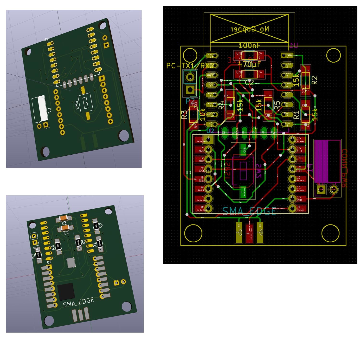
First attempt here here
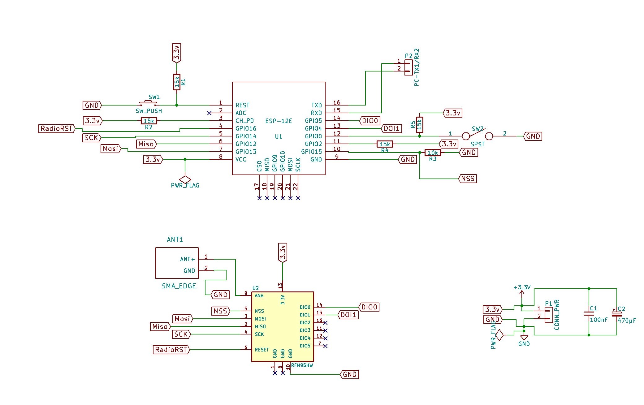
Modifications to the diagram
1 Like
Could you perhaps share the kicad sources on github?
hi
it wold be nice if you could add a LDO 3V3 regulator, so it would be possible to power it from a LiPo
thanks
yes. The spirit of this dev is opensource.
Just need to finish the diagram to get sure.
I’m wondering about shortening the segment between antenna PIN and SMA connector to avoid antenna loss of power.
yes. This is the idea.
There are already made chinese regulators. I wonder, maybe we could add a USB 5V --> Lipo 3.7 v --> Regulator 3.3vv line
Another idea would be to add a solar cell connector + regulator, to allow charging during sleep mode
As I’m new to Lorawan GW, I wonder if it would be usefull to add a buzzer (alerting when WIFI is disconnected or when GW in TRX error) and if it would be usefull to have a small 128x64 oled display soldered on the PCB ( with a switch to reduce energy drain). I’m about to finish the PCB , making 2 extra option would be ok too
Do you think DIO1 and DIO0 could be moved to GPIO9 and GPIO10 , to free GPIO4 and GPIO5 for the OLED display ?
If mods are good, I will post the package on GitHub
Reading all above and since some time has passed with possibly new methods, what would be the best pinmapping for an RFM95 with a Nodemcu 1.0?
Can I just take any GPIO pins and assign them in the LMIC or does it not work that way?
/edit
To answer my own question:
See this post Node with ESP8266 and RFM95W
which refers to this page: http://things4u.github.io/HardwareGuide/ESP8266/ESP-Sensor/esp-lora-sensor.html
// Pin mapping
const lmic_pinmap lmic_pins = {
.nss = 15,
.rxtx = LMIC_UNUSED_PIN,
.rst = 16,
.dio = {5, 4, LMIC_UNUSED_PIN},
}
This is the setup that now works with my nocemcu.
I think the GPIO9 and GPIO10 are intended only for internal use of ESP8266, I had to use the GPIO4 and GPIO5 in my hat to Wemos D1-mini, as in your schematics. I´m using this same hardware for a LUA single-channel gateway or for a node
I want to use a sensor with I2C Pin #4 and 5 on ESP12E, it seems impossible to have I2C (for sensor) and SPI (for RFM95) at the same time?
1 Like
Wemos D1 Mini use ESP12 so all needed pins are there
https://wiki.wemos.cc/products:d1:d1_mini
The trick is to optimize wiring:
- especially DIO pins pulled together with OR diode to GPIO15 not another one, this one has pull down resistor what we need (or leave them unconnected and use LMIC no DIO pin Pull Request
- you can also leave SS pin of RFM95 tied to ground if you only have one SPI device
As you can see, there is some options, just need to choose the one you prefer 
This WeMos D1 shield works fine with RFM95 + I2C, WS2812 Led and PushPutton (Radio Reset is not connected) checkout schematics
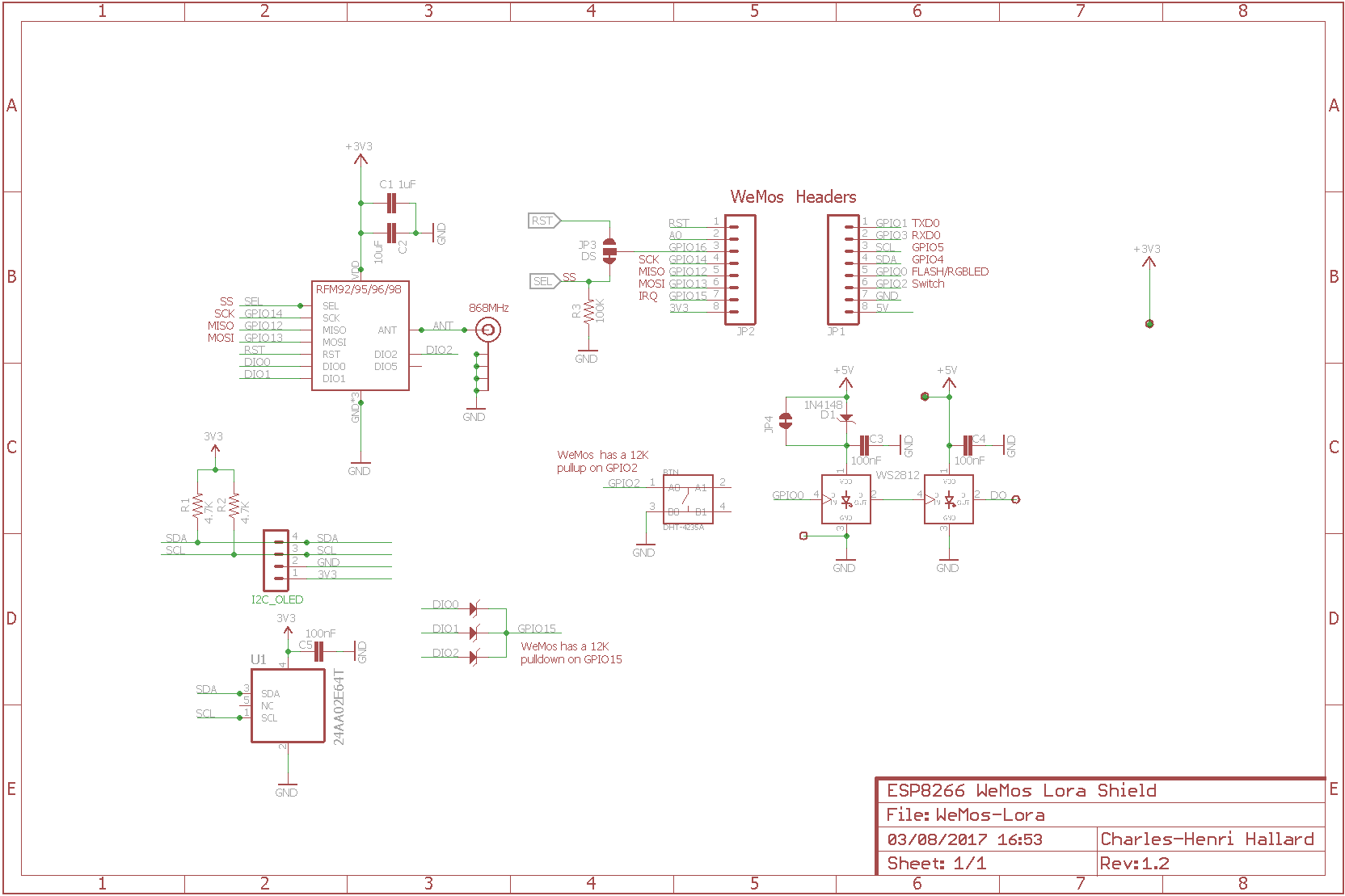
3 Likes
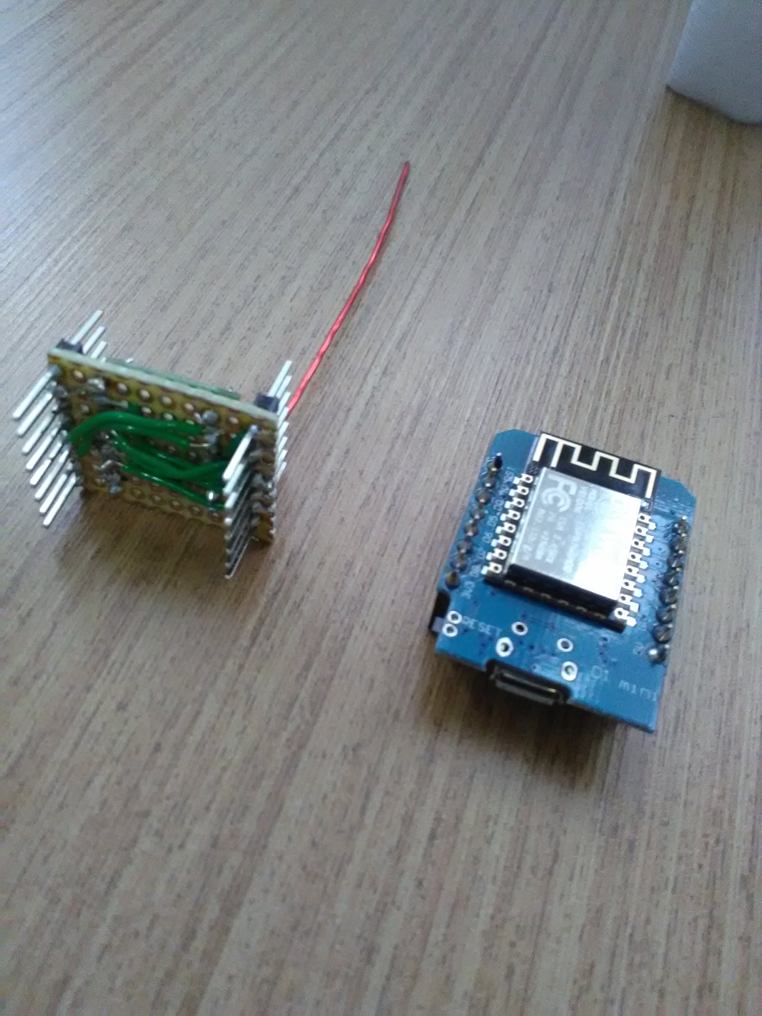
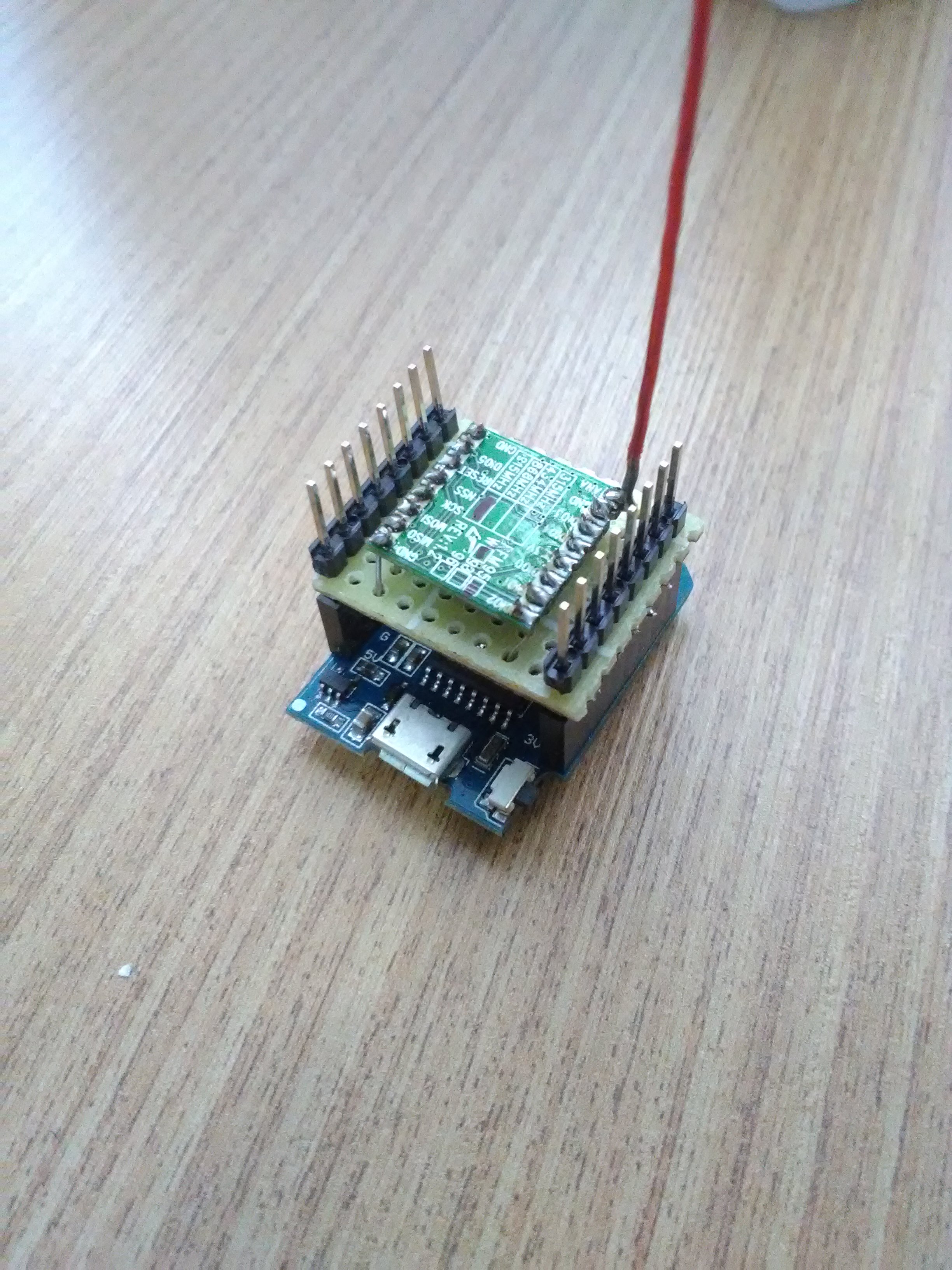
My first hand made node :
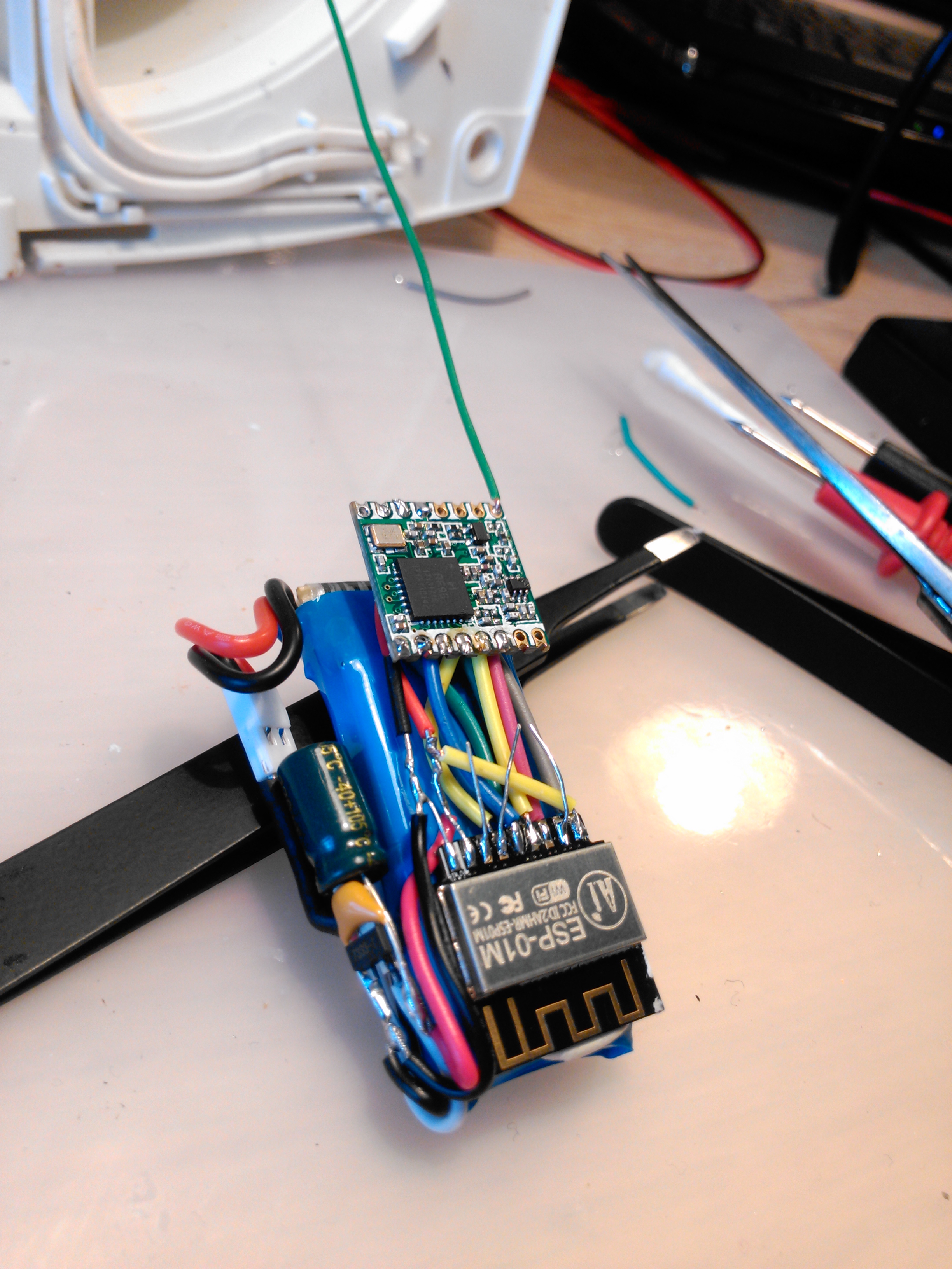
It uses almost no current in sleep mode. Range tests at around 875 meters so far (no los)
2 Likes
Cool, I like the way the wires are routed. Looks pretty clean to put the rfm next to the controller.
What is “almost no current”? would be good to know for battery life purposes.
hi ,
we try to use a RFM9x LORA radio with an ESP D1 mini .we have big problem with wiring the module . in the monitor we see that messages are normally send . but we don t have anything in the data console of ttn .
as you can see we have this in the monitor :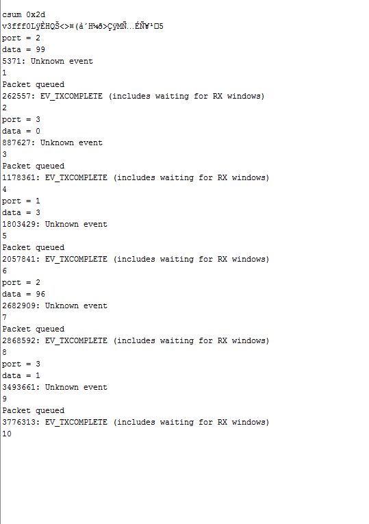
i think the problem is the " unknown event" that happened at each time .
for our pin mapping we do this ;
// Pin mapping
const lmic_pinmap lmic_pins = {
.nss = 15,
.rxtx = LMIC_UNUSED_PIN,
.rst = LMIC_UNUSED_PIN,
.dio = {4, 5, LMIC_UNUSED_PIN},
};
we don’t know if it’s correct or not .
see How should I wire an RFM95 to an ESP8266/WeMos D1 mini?
D8 (GPIO15) -> NSS
D5 (GPIO4)->SCK
D7 (GPIO13)->MOSI
D6 (GPIO12)->MISO
D1(GPIO5)->DIO 0
D2(GPIO4)->DIO 1
const lmic_pinmap lmic_pins = {
.nss = 15,
.rxtx = LMIC_UNUSED_PIN,
.rst = LMIC_UNUSED_PIN,
.dio = {4, 5, LMIC_UNUSED_PIN},
};
seems ok … check again
2 Likes
we do , but no sucess .
i think the wiring is different for our module because we don’t have just lora module but wa have something like this ;
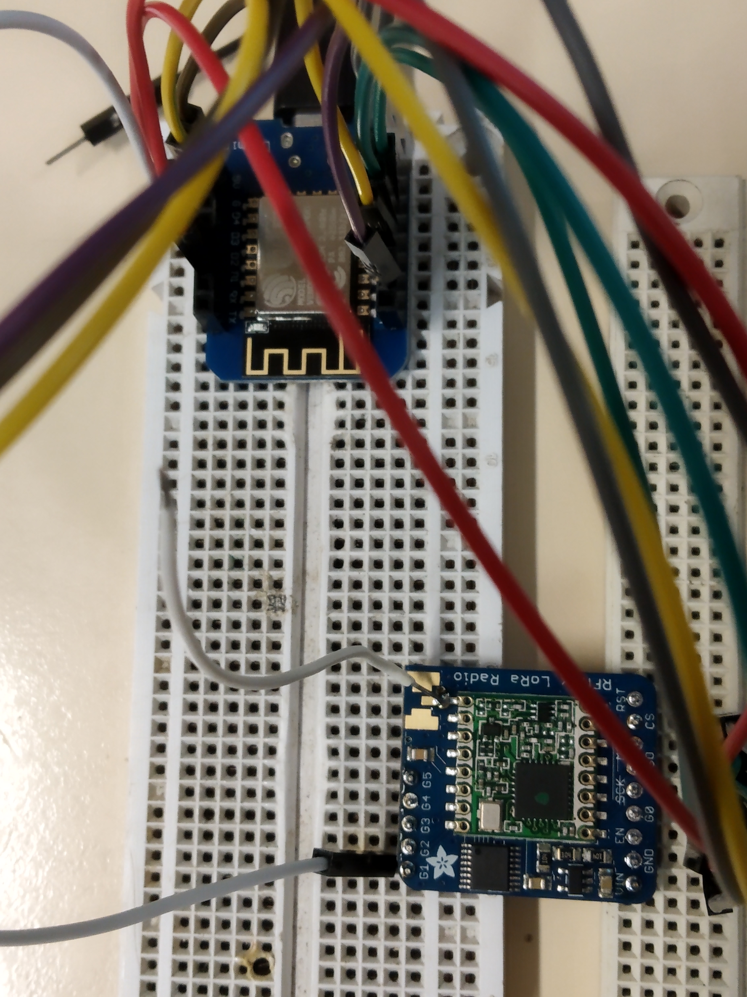
do you tkink this type of module work same as the green card ?
what can be the unknown event ?
I do like you post because you are clearly talk about the PinMapping… which is a bit a confusing topic (GPIO X vs DIO Y vs MISO) an so on…
But I guess you did like to write D5 (GPIO14)->SCK >> GPIO14 right?
Thanks Marcel
It is possble to connet mutiple devices to I2C. Just connect datapins to the CS line of the sensors and RFM. Trip that datapin when trying to read or write to that device.