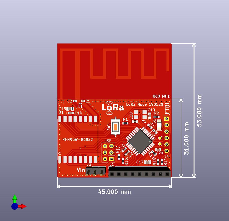
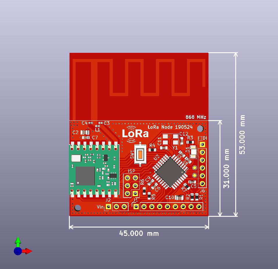
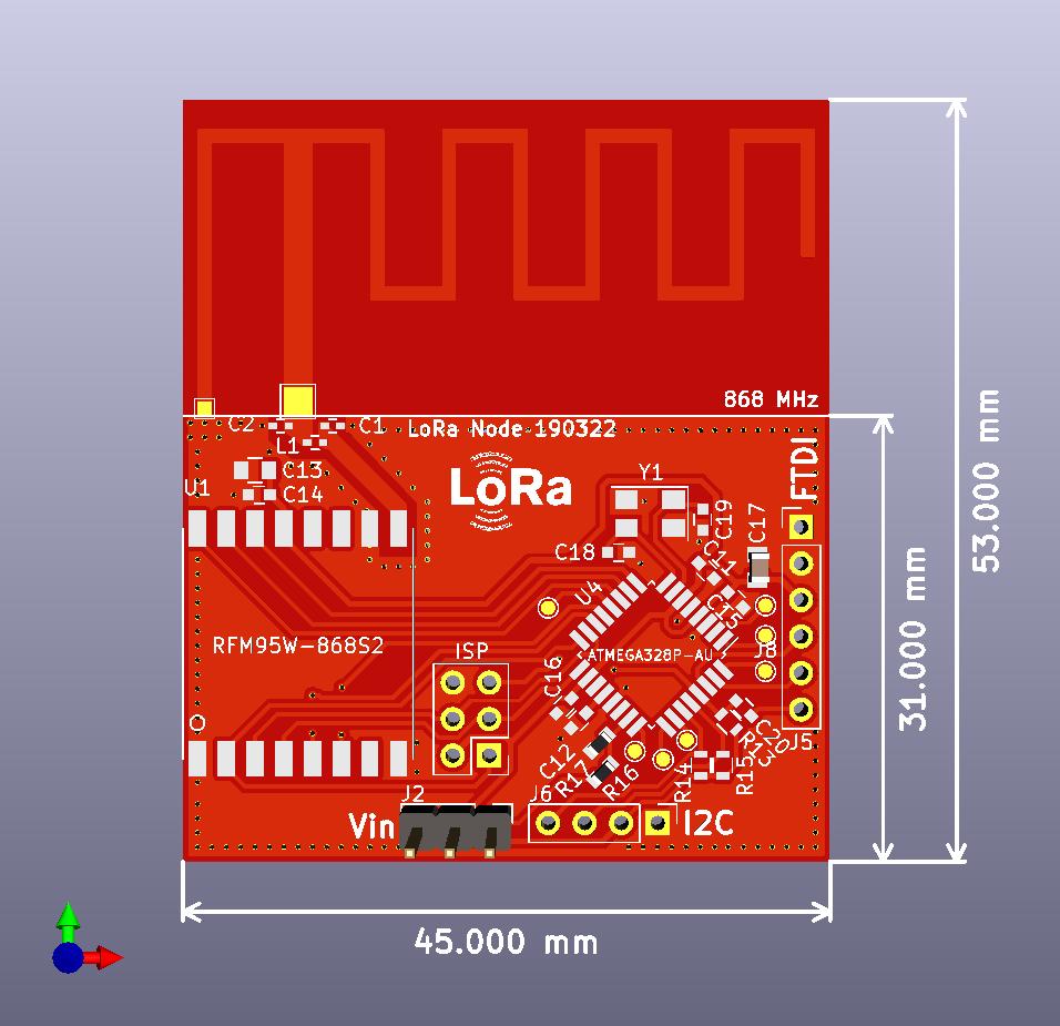
Finally I finished my LoRa node PCB layout. It’s simple, very small size and very cheap, with PCB antenna on 868 MHz. Compatible with FT232RL FTDI USB To TTL Serial Converter. There is the I2C pin header to.
Sorry but no. I realized that my soldering skills degraded very rapidly during few years. So I’m happy when I can finished my few PCB. But especially this PCB is easy to solder, so you can definitely manage this alone
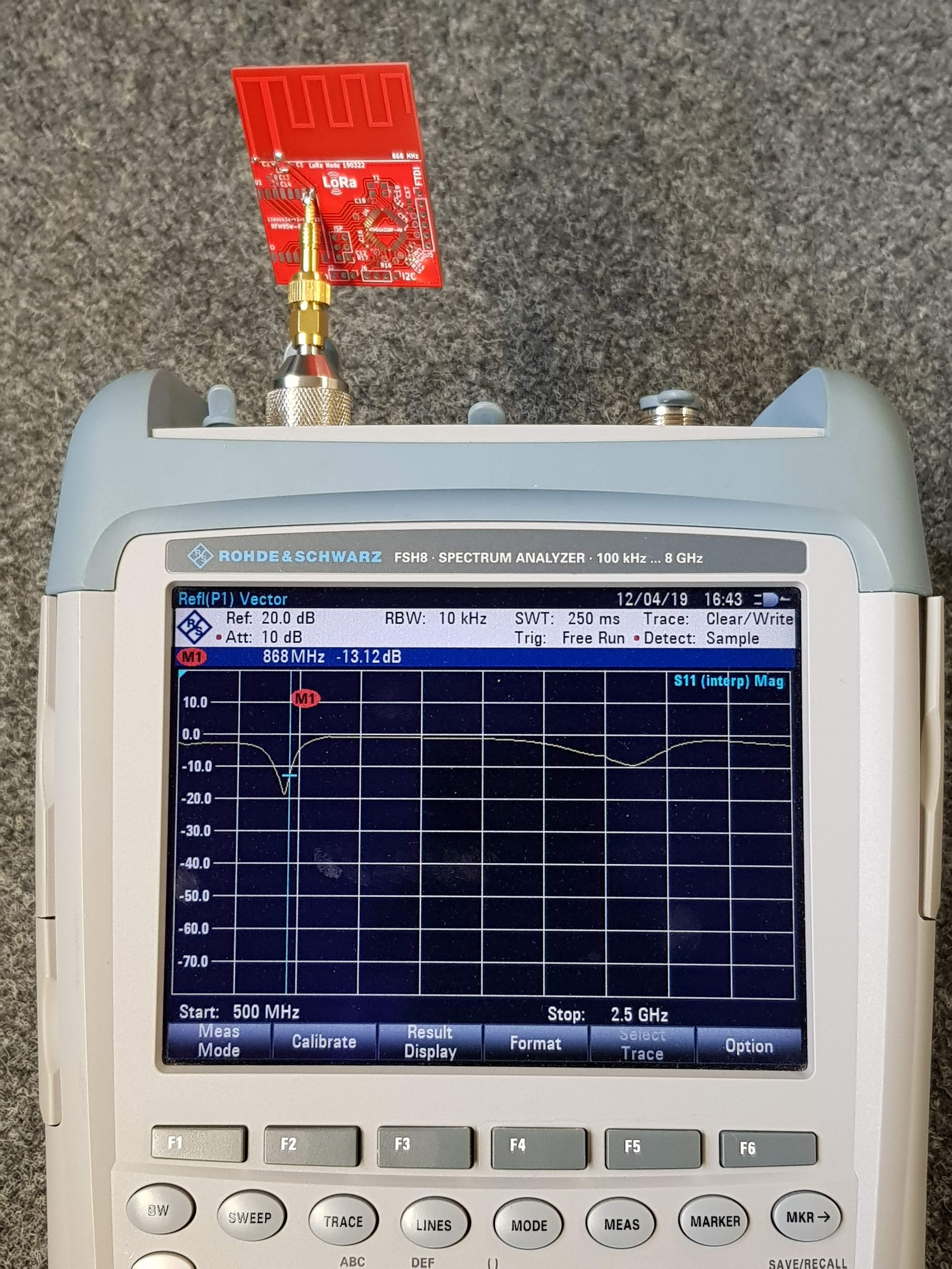
I thing in theory there is no big difference between this and 1/4 lamda wire antenna. But simple wire antenna can change its parameters very dramatically according to size of grounding plane, antenna position and encapsulation. Another big question is repeatability in manufacturing process. PCB antennas have smaller dimensions, are much more stable during the time and are very low cost.
In real world tested performance (RSSI / dropped packets at distance) have you found this antenna comparable with a 1/4 lambda wire antenna? What resources did you use to come to this design? I’m looking to create something for 915Mhz.
The maximum gain of monopole antenna is 2 dB. But this value can be achieved only with infinite grounding surface. Very small surface decreasing gain and most important the resonance frequency. So in best case scenario you can achieve 0 dB gain without resonance frequency shift. PCB antenna counting with finite grounding plane, so i have much better and repeatable results.
But it’s true that I doesn’t test it, so when somebody can achieve better results with wire antenna I will apologize him
Simply great, thanks! It might be nice to make an identical, larger version with only through hole components. That would make it really accessible to a large group.
I added LED and mounting holes. I’m pretty happy with this configuration so i don’t plan to improve this design anytime soon. But good ideas are always welcome.

 :
: