I’m currently looking at this kit (the 868-Developer Kit 2).
The kit includes the RAK831, a Raspberry PI converter board plus an antenna (and an Arduino-compatible board as a bonus). I already own a Raspberry Pi, a power supply and the SD card. Do I need anything else to build a gateway from this kit?
Hi There
I know, they are plenty of of shields for this board don’t blame me.
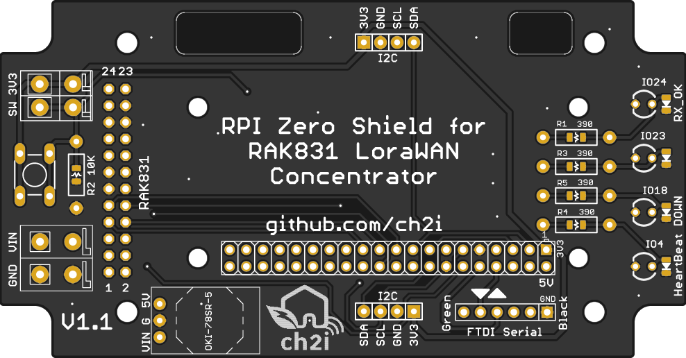
But this week I ordered one RAK to build small indoor gateway. Based on full working IC880a RPI shield, I needed same features like FTDI, I2C connector, Power Off switch and LEDs. I placed as option Murata DC/DC 5V step down (cut wire pad on bottom is you place it). Will use same software, but smaller board size. And for those beginners, all components can be soldered thru holes, so you can avoid any CMS soldering
I also made 2 holes to see RAK LED, not sure they are aligned, but should be.
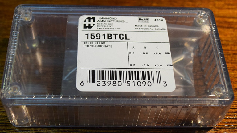
And this as been designed to fit in a nice enclosure, like nice hamond 1591B enclosure.
I Ordered some, need to be tested, keep in touch
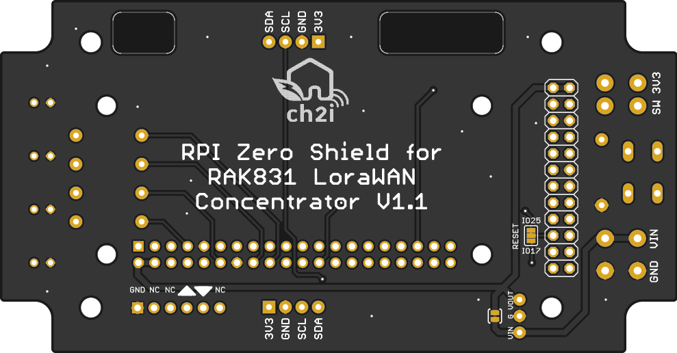
Once tested I’ll share schematics and all but for now, for curious, here PCBs.iolink to order the boards, use at your own risk for now. Not tested
PS : Design update to select SX1301 reset pin from GPIO25 or GPIO16 as mentionned @kilobyte (default is GPIO25)
That is a complete gateway if you include your existing Pi and peripherals. You will probably want to protect the gateway with some sort of case just for general handling or enclosure if you are putting it outside. This will be an IP56 or higher I guess? I have just been over the process of hardening my own gateway to survive outside - HERE
My experience with Kersing’s packet forwarder using the resin.io OS on a Raspberry Pi2 has been very uneventful for a programming newbie, I recommend!
I think the enclosure exist for IP65 (need to check) but for outside, a hole for antenna is not the best solution.
Except may be soldering something like this on RAK board to have clean GW
or this waterproof IP66 one and some tweaking
will check if it’s do able once I’ll have the boards in hand
Oh and now it comes even easier.
Just received 2 of these boards PRE-ASSEMBLED with PRE-INSTALLED SD card
It took me 25min to figure it all out and 1,5 hour to wait while my config file was merged on github and I’m up and running.
You only need to run the install.sh file and create a new gateway in the ttn console, add your config file on github and wait till it’s merged.
I was attempting to follow the Quick Start Guide, which uses the FTDI SPI USB Bridge. The guide instructs you on how to connect it to your linux box and verify the device is working over the bridge.
I was able to connect the RAK to my linux machine as documented and the program finds the unit fine. Everything worked up to the last step where you run the “test_loragw_rx” program which is supposed to test the units receive function and print out the RSSI, SNR etc.
I’m using my RN2903 which is set to 923.3 Mhz SF12 and sending some packets but the RAK never receives anything. I can see its PWR and RX lights are on, but no joy.
Has anyone used these test to verify the boards is working ? It seems like this was all set-up for 868Mhz kits…
I was hoping to verify this worked before buying the enclosure and pi board etc…
RAK831_LoRaGateway/lora_gateway/libloragw $ ./test_loragw_rx 923.3
Beginning of test for loragw_hal.c
*** Library version information ***
Version: 1.5.0; Options: ftdi sx1301 auto-check full no_brd private;
Ok, so this turned out to be a configuration issue with my RN2903, I had not set the sync word to 12, it was still at the default 34. Once I did that, the RAK831 detected and displayed all the packets from multiple RN2903’s on different frequencies.
Received my RAK831 board today . 6 weeks since I ordered but almost 1 week at the start was lost due to me ordering during “Golden week” and 1 week at the end due to customs. Import fees were ~38EUR which is expected.
Will unfortunately not have time to build my gateway today, but hopefully later this week.


 . 6 weeks since I ordered but almost 1 week at the start was lost due to me ordering during “Golden week” and 1 week at the end due to customs. Import fees were ~38EUR which is expected.