The hard RAK831 cafe part 3

hardRAK831cafe3

previous parts of this topic :
The hard RAK831 cafe part 1
The hard RAK831 cafe part 2

hardRAK831cafe3-2

HARDWARE
where to buy ( choose the right frequency for your country !) :

converter PCB’s - the boards between gateway board and Raspberry Pi:

SOFTWARE

RAK support forum

In this software, RAK developed a config UI for users to change frequency, LoRa server, and WiFi very simply. Now, you only need to type a command , and will not have a mistake of configuration.

image
image
image

2 Likes

Can somebody tell me what the value of these two resistors in the antenna trace should be? Are they 0 Ohm?
a009913b5205c549ccc97dbc543c8e340ee28bfc
I am getting only limited range and suspect damage there. The board above is from a post by @Charles earlier but I also did soldering on the connector… (it had come loose)
/edit never mind, I think they may be capacitors

Looking at your picture the PCB seems damaged (SMA antenna connector PAD missing) and PCB not cleaned. Difficult to see the details of the cable and how it is soldered, but this may be a suspect of your bad range.

The two components in the antenna path could be 0 ohm resistors but also inductor(s) or capacitor(s). SMD resistors usually are black and SMD capacitors usually are beige to dark brown. These two components are white however.
Probably best to contact RAK Wireless directly (see contact info at bottom) as a schematic diagram seems not publicly available. (Please share any feedback on what these components and their values are.)

Been there. I accidentally de-soldered the last of those two components when replacing the RP-SMA with a SMA connector. The component was missing after removing the RP-SMA connector. I luckily found it back on my solder sponge and was able to solder it back into position. :blush:

RAK831%20antenna%20component%20removed
Oops (the missing component, cleaned from solder, lying on PCB).

RAK831%20antenna%20component%20remounted
Component remounted.

2 Likes

Thank you for all the info.
The components are white without any markings. They measure no conductivity for dc so I guess they are C’s and probably fine.
The image I posted was actually not of my own gw, it was just one I grabbed from another post. However I had to resolder the connector after I found that the center pin had wiggled itself loose for the pcb. Mine does look a lot cleaner but I think there may be other damage to my gw, maybe even a damaged rf path from operating with a an antenna that was effectively disconnected.
I tried several cables and antennas now and am quite sure the problem is somewhere in the gw. I happen to have a second gw here and that one outperforms the rak by a lot.
I guess getting in touch with rak could be an option but if the device is really damaged internally I suppose I am just screwed.

I got a new raspi 3 with RAK831 and I set it up (hopefully correct) but how can I verify whether it is correct configured and operating?

I created a gateway in the things network with gateid and router address and I get the status = connected.
I also see on the raspi sys log the following entries

JSON up: {“stat”:{“time”:“2019-01-05 13:25:35 GMT”,“rxnb”:0,“rxok”:0,“rxfw”:0,“ackr”:100.0,“dwnb”:0,“txnb”:0}}
Jan 5 14:26:06 ttn-gateway ttn-gateway[507]: INFO: [down] PULL_ACK received in 46 ms
Jan 5 14:26:06 ttn-gateway ttn-gateway[507]: INFO: [down] PULL_ACK received in 150 ms
Jan 5 14:26:06 ttn-gateway ttn-gateway[507]: INFO: [down] PULL_ACK received in 46 ms
Jan 5 14:26:06 ttn-gateway ttn-gateway[507]: ##### 2019-01-05 13:26:05 GMT #####
Jan 5 14:26:06 ttn-gateway ttn-gateway[507]: ### [UPSTREAM] ###
Jan 5 14:26:06 ttn-gateway ttn-gateway[507]: # RF packets received by concentrator: 0
Jan 5 14:26:06 ttn-gateway ttn-gateway[507]: # CRC_OK: 0.00%, CRC_FAIL: 0.00%, NO_CRC: 0.00%
Jan 5 14:26:06 ttn-gateway ttn-gateway[507]: # RF packets forwarded: 0 (0 bytes)

—it looks like the the communication between the LoraGateway (packet forwarder) is established. However no data is transfered!!!

I tried to setup a lora node (lora hat module with raspi (model 2b) - sending data to the Gateway and then forwarding it to the ttn-network, however I see no data transmitted.
It looks like the lora node is also sending data but I don’t see the data in the ttn - trafic overview.

Any recommendations how to verify my setup? Are there any test scripts available?

Are you nodes & GW on same frequency plan?
Is your 831 the right one for the freq plan being used?
Which 831/Rpi s/w build are you using - does build confirm concentrator has been reset & started correctly?
What h/w config (jumper wires or an interface bd between RPi & 831…which one?

I think they are on the same frequency plan (eu 868Mhz)
From raspi with rak831 I get the info from syslog
INFO: radio 1 enabled (type SX1257), center frequency 868500000

I am using the sw build which was shipped from Aliexpress (arrived a few days ago) Version is 4.0.1

About the hw config - everything was preassembled and should be connected correctly. (I hope so)

Have heard of a few folk having issues with shipped image/revisions, and I note RAK also now ship a Pilot pre-configured for use with IoTinabox. 1st thing I do with my RAK builds is scrap image and rebuild with either the TTN Zurich config (Technoblogy had a good simple instruction to follow - just make sure you change reset pin option to match RAK vs iMST card) or one of the Hallard images from Github - works just fine then :wink: A 5- 15min exercise following simple instructions…

ok - may be an alternative to start from scratch with a new image - I will check github to select the right one (It sounds the Hallard images are fine)

Do you have a link to the images? (On hallard I find only raspi zero - but I am using raspi 3)

@Charles has done a fine job of evolving his image over time - its simple script/text menu option driven approach covers options for various RPi’s and various interface boards supporting the concentrator cards…with or without various embellishments inc RGB LEDs etc. Fire up the software on the Pi of choice and work your way through the options following your nose and it should work fine (I have used with RPi2, RPi3, RPi3B+ & RPi0W, self builds or RAK cards or RAK PIlots, also editing startup script to select the mp_packetforwarder vs poly_packetforwarder in most cases :slight_smile: )

Note: The s/w will auto detect the RPi used and report back to you, if using the RAK Pilot or discrete RAK cards with the ‘official’ interface card you will see a menu option to choose something like IIR “RAK Official Interface Card”, just pick that! :wink:

ok, I do my best - and many thanks for your support

Link here: https://github.com/ch2i/LoraGW-Setup

Also referenced from here: https://github.com/hallard/RAK831-Zero

:slight_smile: the raspi3 - rak831 based gateway is now sending data the the things network console. Thanks!

now the next step has to follow - to connect a lora node to the gateway (some challenges with the ttgo esp32 based node and the lora gps HAT raspi 2b based one.

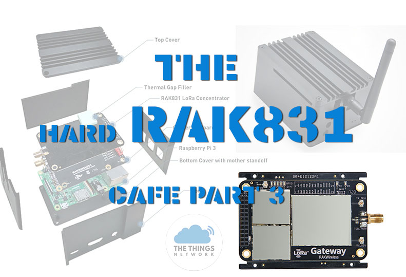
Okay, after a couple of weeks of serious struggling, I got my RAK831 up and running. I used this repository since it seemed the most current:


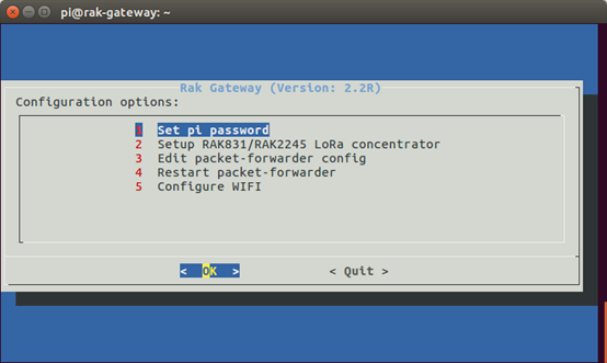
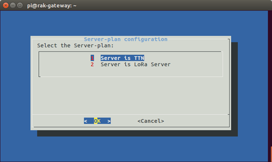
After more digging, maybe I should have used the Kersing repo, but I believe that I have this one working okay. I’m in the US, so I had to fix my .json files and also added the LUTs for the radio… My gateway is showing up on my console, and appears to be working. Currently I have it in beacon mode, but it isn’t sending any because the ublox module isn’t putting out UBX messages (I’m a code digger). Unless I’m missing something, that shouldn’t otherwise prevent the gateway from working as it should.

I’ve got several kinds of node devices, a RAK811 tracker, a RAK811 WisNode (these came with my “kit”). I also have a couple of Arduino (Bsfrance) LoRa 32u4 II ver 1.2 modules. I’ve come to realize that all of these devices come with their own quirks and none really work in the way that one would expect, without some soldering or jumpering.

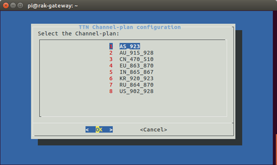
Since it seemed the easiest place to start, I plugged in the WisNode and tried using the AT commands from an example. I seemed to get it to transmit, but I think it’s going to need a lot more AT commands than the examples indicate. The real problem is trying to convert all the examples that seem to be tailored for EU usage to US usage. BTW, I’m certain that I have US915 equipment and my gateway is using a US915 .json file for the frequencies.

Looking at the logs, it appears that most of my transmissions have resulted in CRC errors, when even noticed by the gateway. OTOH, I did see a couple of log messages showing a good CRC message was received. I have registered my application and device with ttn and have been attempting to use ABP activation since that seemed the easiest to test. I understand that OTA is preferred, but right now I’m just trying to get packets to my application.

The ttn console does show that my gateway has received two packets, but nothing shows up in the traffic box. I guess it goes without saying that the application itself has seen absolutely no data of any kind yet. I believe I have all my keys correct and in the right byte order. I understand that when including them in an Arduino program, they need to be in lsb order, but I believe the WisNode wants them in msb order.

Can anyone recommend what I should try next with the WisNode? Should I be trying one of the Arduinos instead? Or the RAK811 tracker (old version apparently). I don’t mind struggling, but I’d really like to make some progress here. Sorry for the long-winded post, but I’m trying to be thorough. Thanks.

this is not the right topic for your questions :wink:

Okay… I don’t really understand why you say that, but okay. Should I create a new thread? I thought this thread was about getting the RAK831 gateway up and verifying that it works. I apologize for misunderstanding the purpose of this thread.

I guess I shouldn’t have been asking questions about nodes here. :wink: That said, I’m getting it figured out now. Turns out that my global_conf.json wasn’t quite right for the US region. I found the “official” one on GitHub and now the gateway starts on the first try every time, so far.


I modified my local_conf.json to turn GPS back on, without beacons, but it still outputs that error message about the time being off by 40 years [# Invalid time reference (age: 1547348495 sec)] I’m sure that’s because of the receiver only putting out NMEA sentences and no UBX messages. When I fix the library, I’ll try to issue a patch/pull request. Everything seems to be working now with ABP joins. I can even recieve queued downlink requests on my wisnode.

I guess I’ll start a new thread in the proper place describing all the AT commands that need to be issued to the wisnode to get the right transmit frequencies mask, data rate/spreading factor etc to the RAK811 wisnode in order to have it working correctly in the US915 area. What a struggle, reminds me of trying to get x windows running in Linux back in 1995. :slight_smile:

If you use my fork of the library that has been ‘fixed’ (== reinstated)

1 Like

Okay, thanks for that information. I hadn’t discovered that you had a fork of the code until after I had picked one and set about fixing it up to work for me. It’s my understanding that yours has some advanced features, in terms of how the traffic is handled on the internet. When I have some more time, I’ll probably switch to your fork. In the mean time, I have a practical use for my gateway and I need to concentrate on getting end node devices figured out. I’m searching for the perfect dev board that can be powered by batteries as my plans include fixed position sensors to monitor water levels in the local drainage system to supplement the sparse county sensor system.