That are about 3024 pieces.
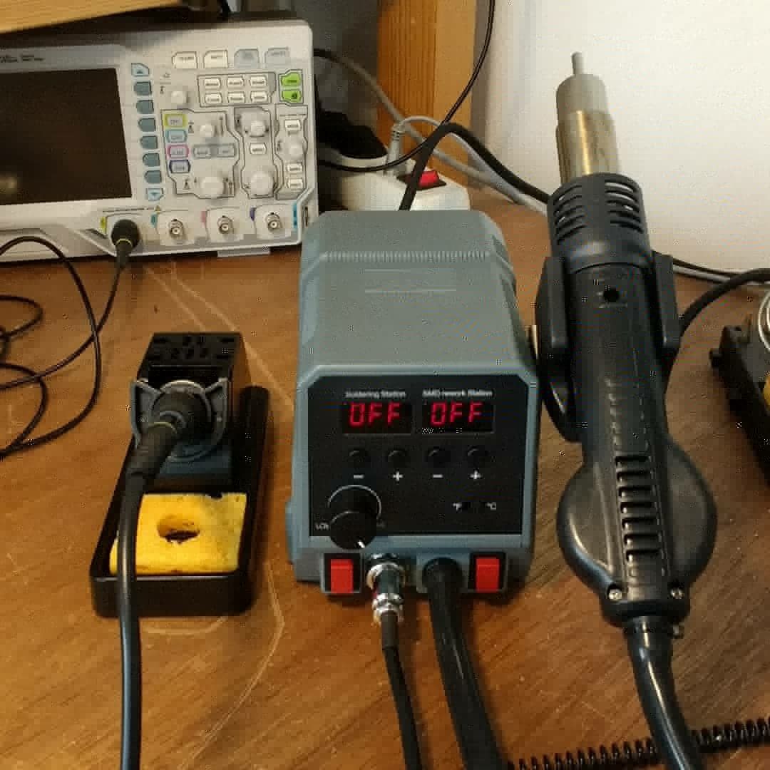
Took a large bite out of my hobbybudget savings yesterday. For years I have been working with SMD parts on various projects but a lose BME280 was to small for me to handle with my Weller soldering iron. So went to my local electronics store and bought this Velleman SMD hot air rework station.
Removed the BME280 sensor cleaned the pads and applied fresh solder (don’t have the SMD solder paste yet), a few brushes of hot air and the sensor was mounted again.
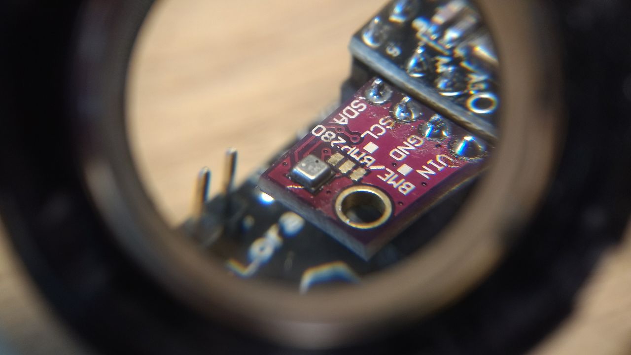
A few hundred samples where made with the refurbished BME280 and matched with a reference BME280 and there where no shocking difference in measurement values.
Think I should have bought a hot air station years ago 
4 Likes
did you replace a few hundred smd BME280 's … ? 
2 Likes
LOL, I didn’t ![]()
I let the refurbished BME280 make a few hundred measurements over a hour time to compare to another BME280 to so if my handy work didn’t damage the sensor.
1 Like
Hi guys,
I was lucky to acquire cheap (really cheap) a air/water heatpump for my swimming pool.
Now the only problem it has is that it doesn’t turn off when the selected temperature is reached.
When i turn the thermostat lower then the actual water temp, i do hear the thermostat clicking, but no relay is switched and I don’t see any change in current consumption (which i expect?).
It’s a complete analog device, so no electronic controlboards or whatsoever.
I would like to “upgrade” this with an arduino/esp8266/esp32 and make it a bit smarter, but I need to now how it technically works.
Turning off when the temp is reached, what does that imply? Turn off the compressor and leave the fan running, or also turn off the fan?
Tips highly appreciated,
Eric
start with the exact brand/type of that air/water heatpump, maybe a link to the manufacturer/schematic ?
The most relevant link i can find is this one https://www.heatpumps4pools.com/Second-Hand-Units/Duratech-Eco12-Second-Hand-Pool-Heat-Pump
Mine is labeled: “ECO HEAT PUMP” model “ECO-12” exactly the same as pictured in the link
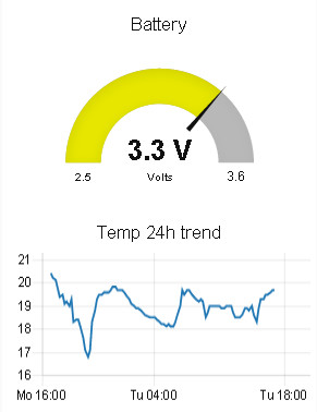
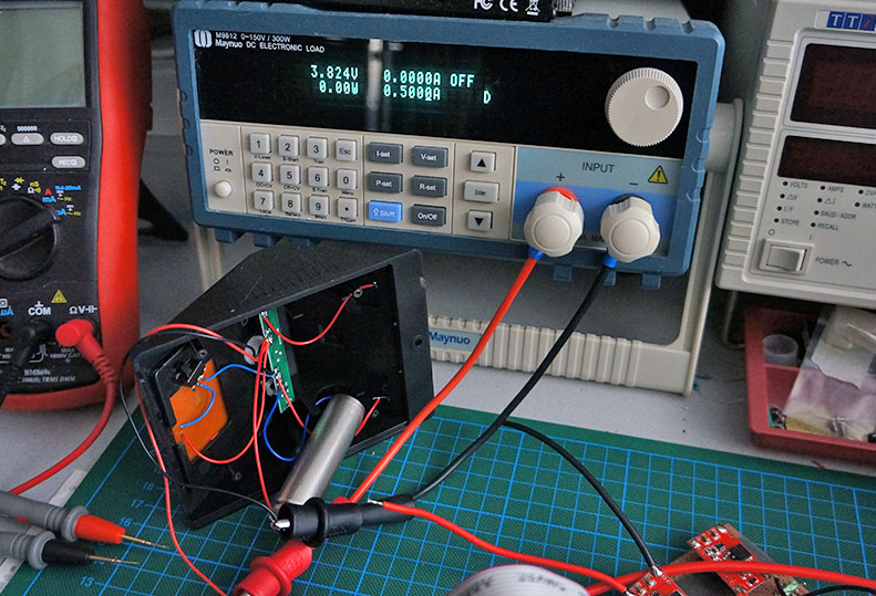
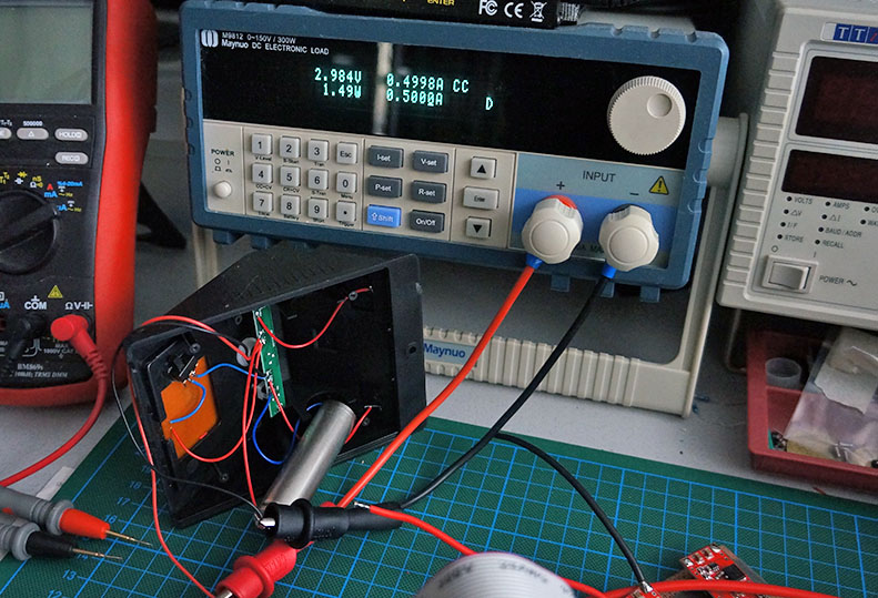
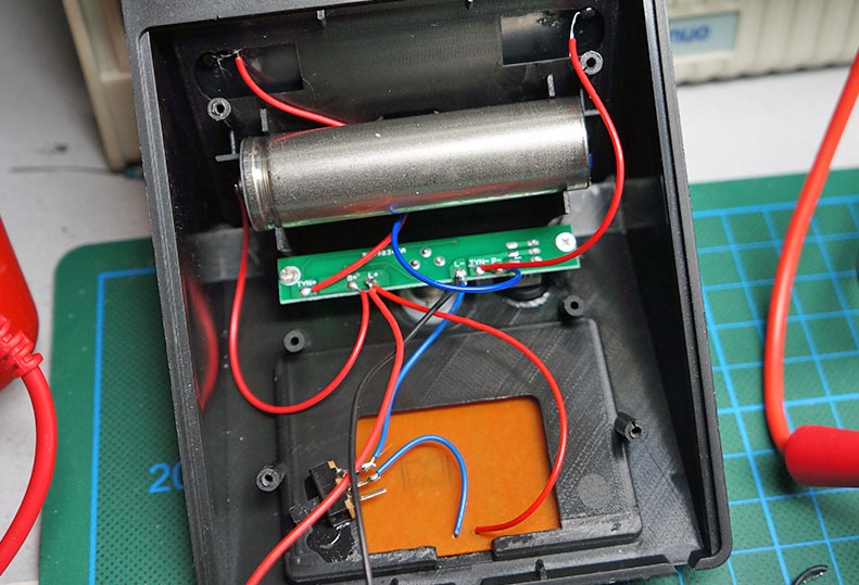
So I have had over 1 year service out of a Charles Hallard low power node using a single LiFePO4 cell. In fact the cell still measures 3.3v which is the voltage it shipped to me at and it has never been recharged.
Today I discovered that there is a TP5000 charge controller which has a solder jumper to select between 3.6v or 4.2v final charge voltage (LiFePO4 or LiPo/18650 chemistry) which has a wide enough input range to take a 6v solar panel. Given the small power consumption of a sleeping/low-power node, directly connected to a LiFePO4 cell unregulated, is this not a perfect solution for a fully autonomous node, deployed for life type? Trickle charge 1 or even 2 parallel cells when light is available for constant 100% state if charge? Does anybody know of quiescent current characteristics of these modules, for example without the charge LED?
2 Likes
I ordered some of these last year.
In case the LED doesn’t work: my boards (from above shop) came with the wrong LED: common cathode but must be common anode (luckily not soldered).
Solder jumper F open: 3.6V (LiFePO4) and closed: 4.2V (Li-ion/LiPo).
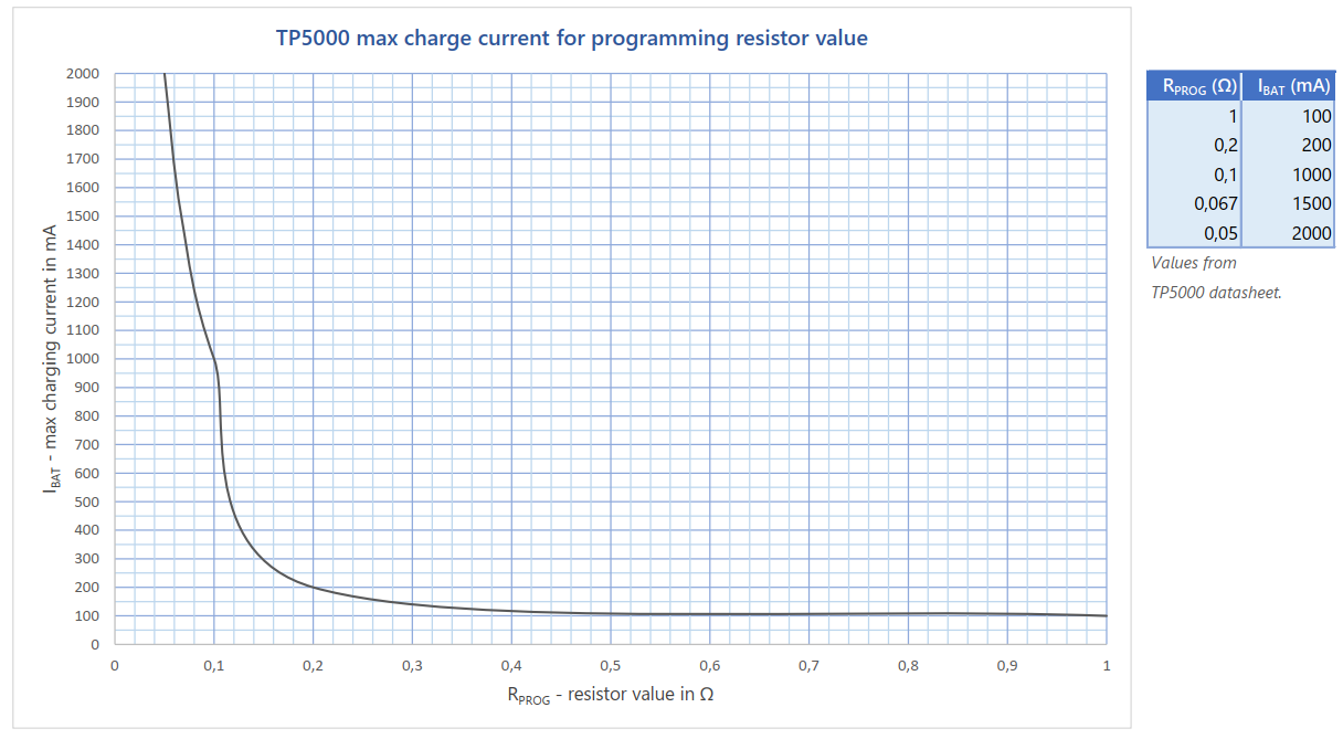
The charge current can be adjusted by replacing a resistor, but requires very low resistor values < 1Ω.
Note/Warning: The board is default configured for 1A charging (0.1Ω resistor).
The default charge current for my Soshine 14500 (AA) 700mAh and 18650 1800mAh cells is 300mA. For fast charging: 600mA for the 14500 cells and 1.5A for the 18650 cells. For charging 14500 LiFePO4 cells the charging resistor should be replaced with a higher value (see below graph).
Attached is the TP5000 Datasheet (translated from Chinese).
(First resistor value for Ibatt 100 mA in the table on p7 got lost in translation, it should read 1Ω.)
TP5000 Datasheet (translated from Chinese).pdf (778.7 KB)
I made a graph from the resistor values in the datasheet. The values show a strange non-linearity so I wonder how accurate they are (or it may be Excel related).
Nice. Just curious:
- What size (probably 18650) and capacity is your LiFePO4 cell?
- Is the node doing any measurements?
- How often does it transmit messages?
Yeah, it is a 18650 LiFePO4 and I don’t recall the capacity. I do seem to recall not buying the most expensive as it was my first experiment with the chemistry un-regulated on a 3.3v MCU.
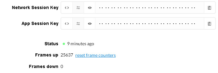
The node has a BMP280 which it wakes and polls every 15 minutes so 96 cycles per day. Here are some snaps from browser views today, the battery voltage and the frame counter. This node was reset 1.5 months after deployment by a curious kid who asked what the little button did after he had pressed it! How human 
It is running at 96 transmits per day for over 12 months at this stage!
1 Like
Yeah…
As I said in the other thread, mine is approaching 4 months with a 700 mAh Soshine, posting data from a BME280 every 5 minutes…
I disabled ADR a couple of days ago (using a downlink command), as I realised that due to some recent change in TTN, every uplink was generating a downlink 
2 Likes
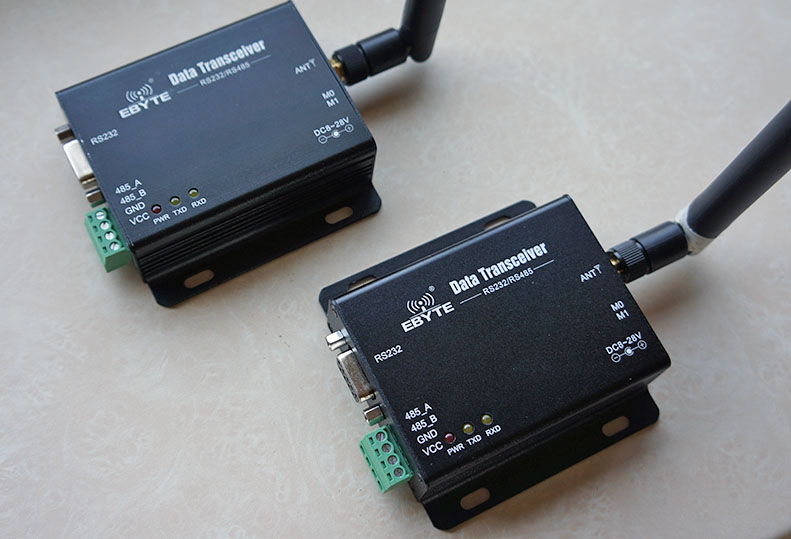
2 x LoRa SX1276 RS485 RS232 Long Range rf Transceiver E32-DTU-868L30
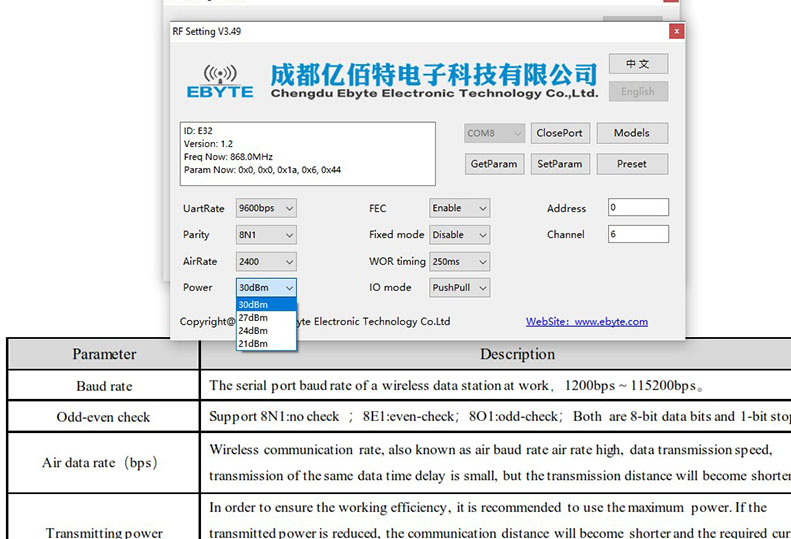
ordered these for making my own very short cables, for programming the units I use this USB- RS232 cable

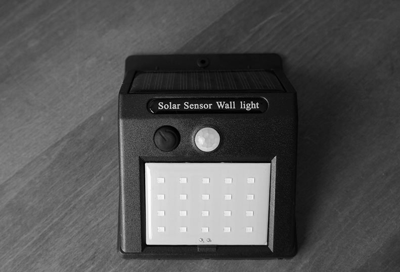
- outdoor solar pir light
- update - didn’t meassure the exact capacity of the battery (yet) but this solar unit seems usable as
an solar outdoor lorawan alarm node enclosure
2 Likes
I want to present you my project 
eAgrar is system for monitoring conditions of plants and for monitoring weather on agricultural fields.
This sensor device is plug-and-play device, it is battery powered and uses LoRa technology for communication. It is used as part of TTN network. Also, there is dashboard where you can monitor all measured data.
Device uses RFM95W LoRa module for communication
I want to ask you to get in link and “Like project” so I can get in TOP20 of Hackaday Prize. It will enable me to keep delevoping this system.
https://hackaday.io/proje…/165235-eagrar-digital-agriculture
So get in link, register and LIKE PROJECT. ![]()
Thank you! 
1 Like
’ Sensor devices send data to multichannel gateway which forward them to database. ’
I have developed system for controlling devices in LoRa wireless sensor network . So even that device is not connected to Internet all time, I’m able to change sleep time, communication parameters and other parameters remotely, without reprogramming device.
can you explain a bit more… is it a ‘protocol’ on top of lorawan … how does this work that you can set intervaltime from a sensor remotely ![]()

can you explain a bit more… is it a ‘protocol’ on top of lorawan … how does this work that you can set intervaltime from a sensor remotely
Yes, it is kind of protocol on top of LoRaWAN and inside of device.
Device is connected to TTN network. Using downlink messages, I’m able to managed how device works. Device can recevice message, take parameters and commands from message, and keep working based on new settings.
For example, if your device is in ABP mode, and you want to change Spreading factor, you don’t have to connect device to computer again and reprogram it. It is enough to send downlink message with needed code and device will update settings.
Thanks for like! ![]()
1 Like
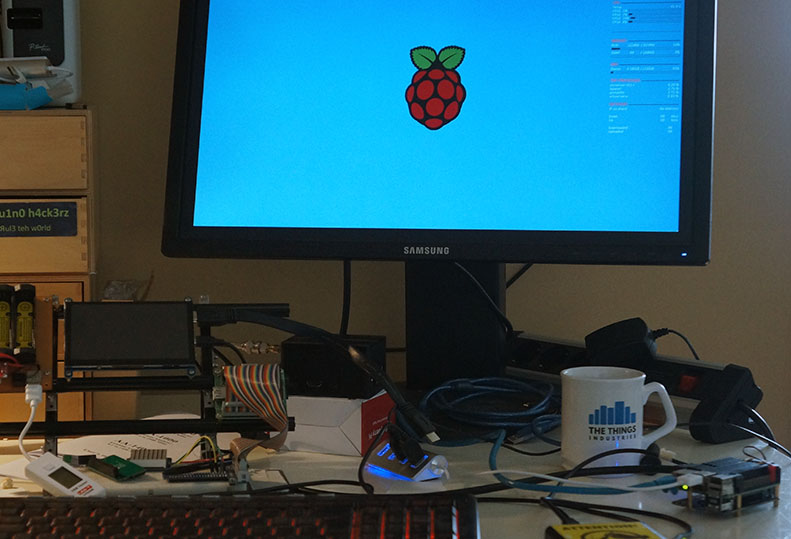
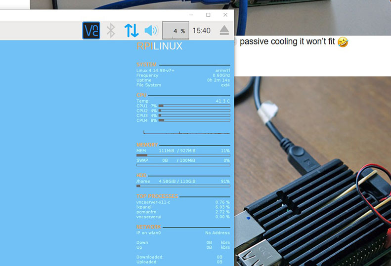
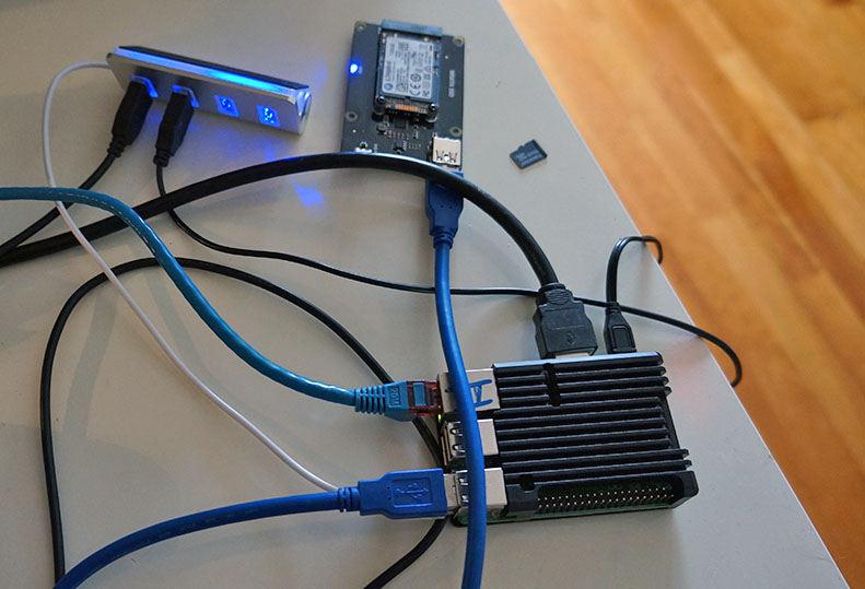
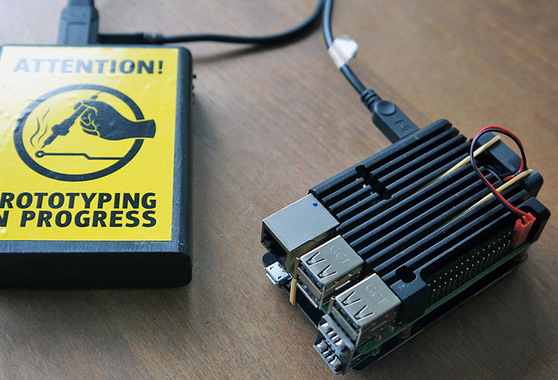
installed desktop widget CONKY on RPI
old cheap tele solution video experiment … now even cheaper 