If the resistor is wrong, you wont be able to access the device at all.
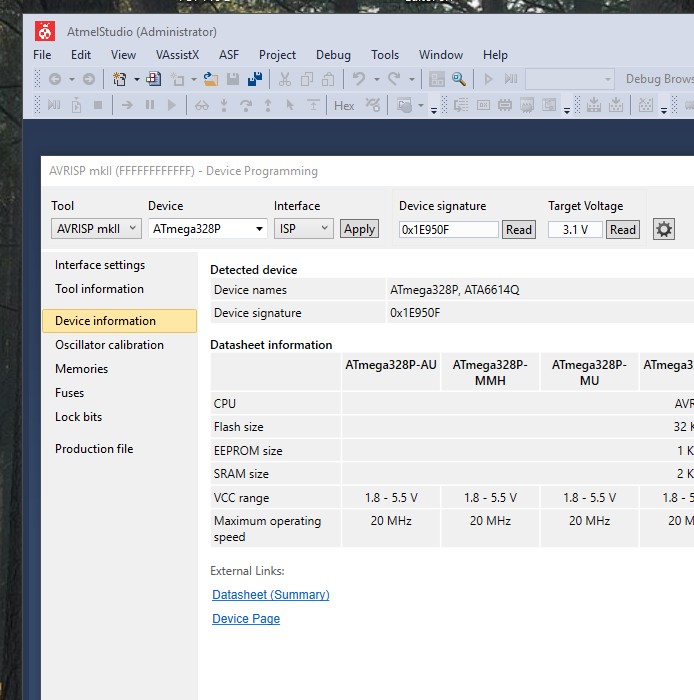
Easiest way to debug I find is to use Avrdudess to see if you can detect the device correctly, it should report;
Detected 1e950f = ATmega328P
If the resistor is wrong, you wont be able to access the device at all.
Easiest way to debug I find is to use Avrdudess to see if you can detect the device correctly, it should report;
Detected 1e950f = ATmega328P
you’re right… the resistor on the rfm works.
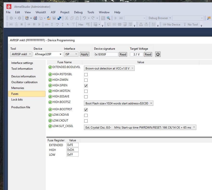
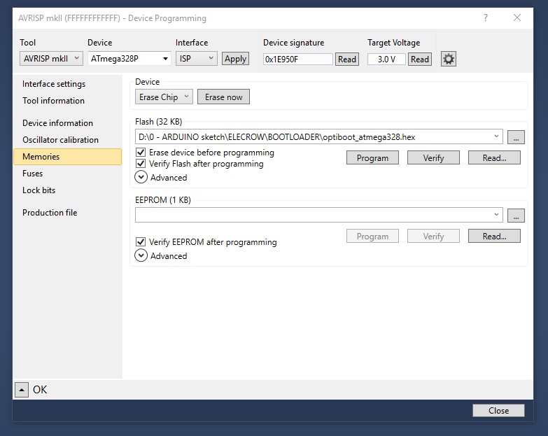
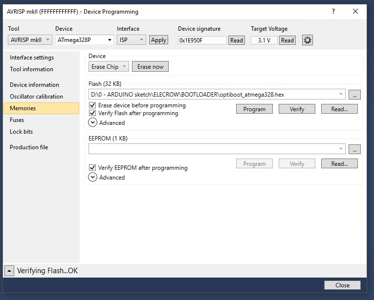
I can detect the processor and I can flash … but don’t know the settings yet… see
There’s your problem straight away Rob…you need at least two but never more than four for decent results! ![]()
![]()
Configuration for fuse and lockbit is here
great !! tnx Charles
you’re welcome,
Just flashed my 2 boards, without any issues  , well after being stuck by resistor forget lol
Look forward to your detailed write up 
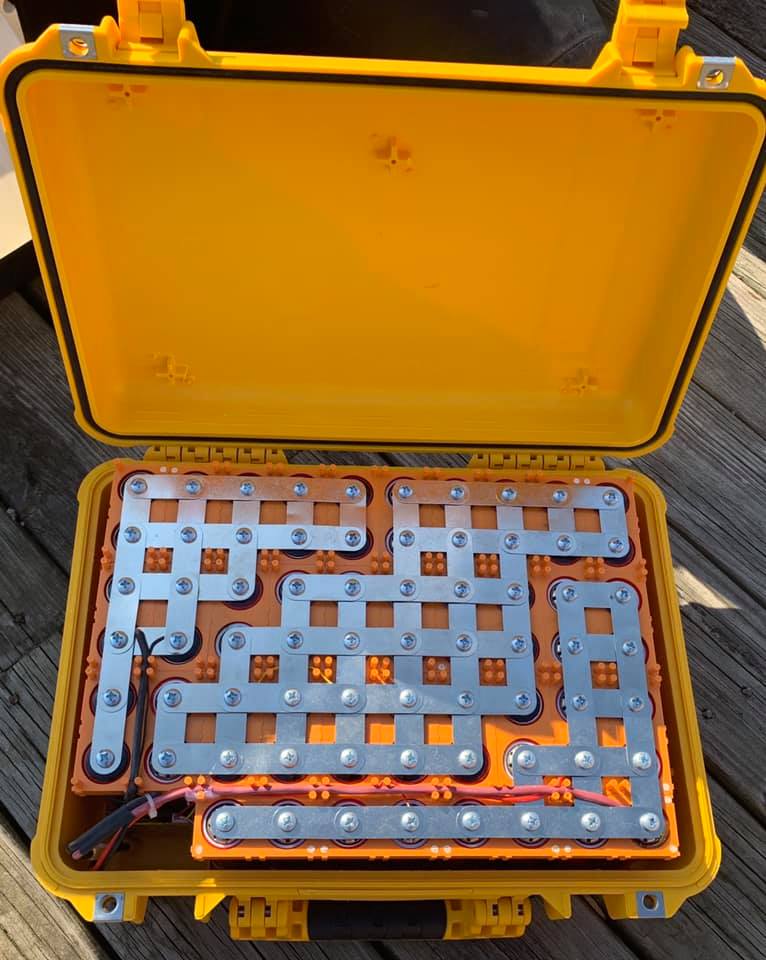
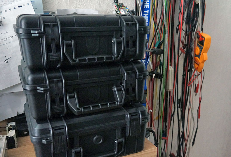
This is what I hope to achieve too some day ( 1.7 kWh portable) … very well build.
In Europe we can expect a lot of power outages in the near future… the hurry to get everyone using
only electricity is a big mistake, and the grid can impossible cope with the demand.
So… create backup systems yourself… new and very fast growing trend…
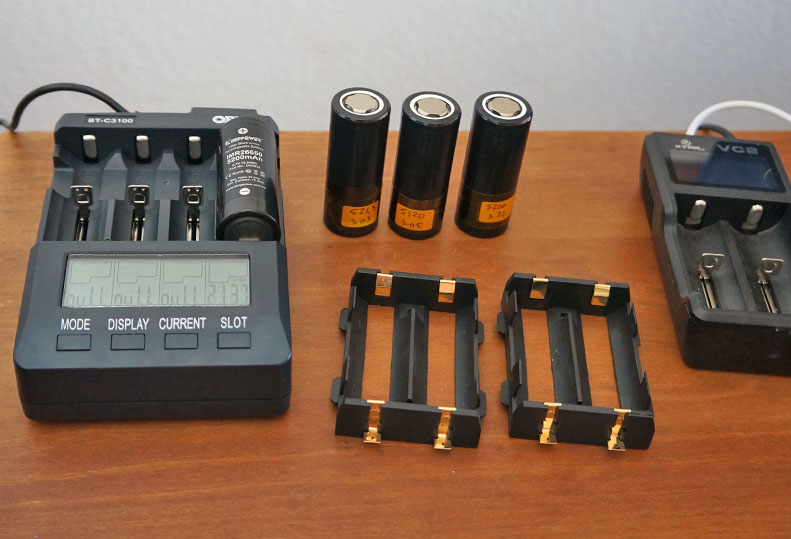
at this moment I’m capacity testing each cell (max 16 x 26650 per unit)
I bought this antenna, to use for my 868 mhz gateway. But there is a label on it, with 1900 written on it. (also on the ali express picture)
How can I detect for wich bandwith this is usefull ?
I have an RTL-SDR. But no spectrum analyzer.
Update: on the detailed page it says 1900 MHz, grrrr Aliexpress is getting worse.
’ This antenna was also designed to transmit on the 900mhz frequencies ’
So maybe it just works ?
finalizing some I2C sensor test node.
Main board is an old design, but small board on right is I2C connected and houses BME280, SI7021 and VEML6075. This enables to measure pressure, temperature, humidity, dew point (still to crack this one) and UV index.
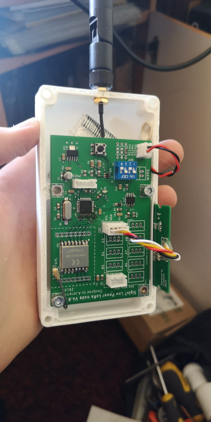
P.S. thinking about making small outdoor node any tips of how to seal box but still allow pressure and humidity measurements. Have seen some ideas around here, but maybe someone has new update.
I still have the idea that flashing optiboot in the lora node didn’t work.
What should you see in the arduino ide for free memory with optiboot when succeeded ?
I would assume the IDE just assumes the length of the booloader for the core that is in use.
The only way it could know for sure, which bootloader was programmed would be for the complier to read the actual processor in use and it does not do that, complile works with no processor connected. .
yes you’re right
I was thinking ’ he the optibootloader is -1.5 kb smaller… you should see that, my mistake ’ 
on the positive side… maybe its working 
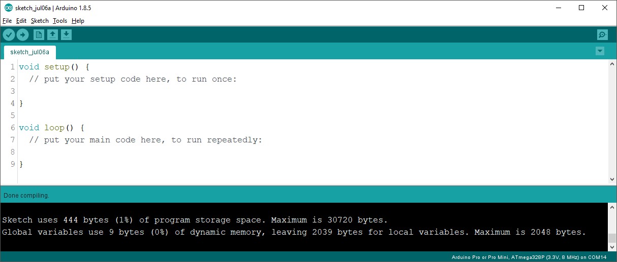
Arduiono IDE, ATMega328P, with different cores selected;
Standard IDE core, maximum is 30720 bytes.
Minicore (optiboot), maximum is 32256 bytes.
I have been swapping to Minicore\Optiboot as I want the watchdog timer to work …
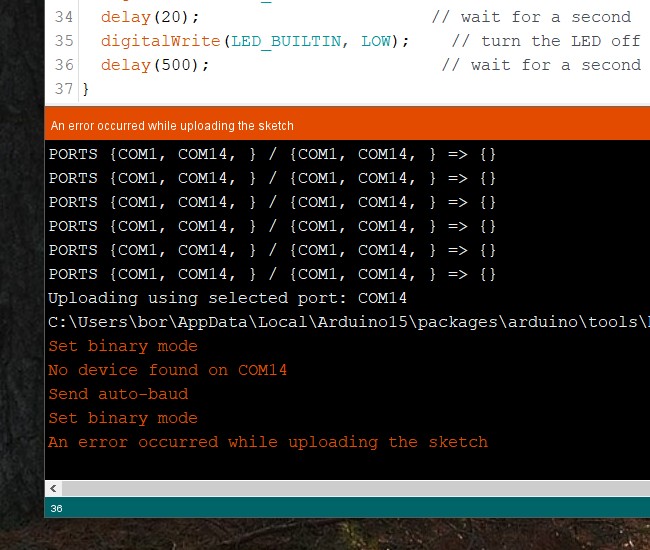
ok so its NOT working …
1 - erasing the chip works, can’t connect anylonger
Which core are you using ?
If the IDE thinks you only have the standard bootloader, cant see how its going to let you use the extra space that it does not know about.
Although the Minicore seems to be the better option, you seem to have to keep using it.
An standard Arduino IDE (not using Minicore) does not see the Arduino, which is fine if your the only person using the Arduino board, but if someone else needs to program it, I think they need to install Minicore.
So I erased (100 % sure  )
)
I burn it again (‘basic’ optiboot)
et voila (that’s french for @Charles
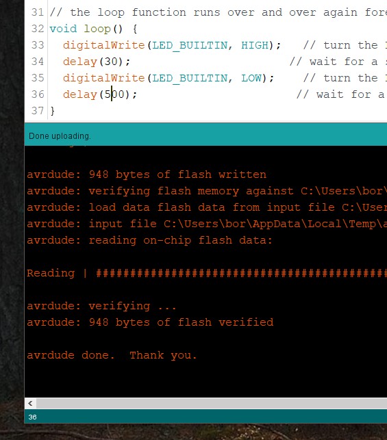
blink works ! … conclusion… uhhhhhhhhhhhh no clue
For Charles bootloader arduino still needs to be adapted as described here? Full Arduino Mini LoraWAN below 1uA Sleep Mode