It’s in the MCCI LMIC instructions …
1 Like
I tried the code provided searching for “Specific AXP192 code”. In order to make it work I downloaded the library AXP202X v1.1.2 and imported into Arduino 1.8.13. The code compiles successfully and I can see on my screen the message "AXP192 Begin PASS".
On an empty project where I only print some chars in the console, I can’t see any difference.
On the otaa example, I get the same error on the 9600 Baudrade, with the only difference that the "AXP192 Begin PASS" message is present.
AXP192 Begin PASS
Guru Meditation Error: Core  1 panic'ed (IllegalInstruction). Exception was unhandled.
Memory dump at 0x400d10bc: 0203a200 00000000 ff7f0000
Core 1 register dump:
PC      : 0x400d10c0  PS      : 0x00060130  A0      : 0x800d1114  A1      : 0x3ffb1f00
A2      : 0x3ffc01bc  A3      : 0x3f4010d0  A4      : 0x00000001  A5      : 0x00000001
A6      : 0x00060320  A7      : 0x00000000  A8      : 0x3f4010d0  A9      : 0x3ffb1ee0
A10     : 0x00000005  A11     : 0x00000000  A12     : 0x3ffc0350  A13     : 0x00000001
A14     : 0x00000001  A15     : 0x3ffb1eec  SAR     : 0x0000001a  EXCCAUSE: 0x00000000
EXCVADDR: 0x00000000  LBEG    : 0x4000c2e0  LEND    : 0x4000c2f6  LCOUNT  : 0x00000000

Backtrace: 0x400d10c0:0x3ffb1f00 0x400d1111:0x3ffb1f20 0x400d1143:0x3ffb1f40 0x400d115a:0x3ffb1f60 0x400d0d1f:0x3ffb1f80 0x400d354b:0x3ffb1fb0 0x400889d9:0x3ffb1fd0
What pin mappings have you configured for LMIC?
Even after checking the git for documentation I am not able to declare the lmic pin configuration for my board. In the first place I don’t know where to modify (in which file).
1 Like
It was further down in the configuration section you linked to: GitHub - mcci-catena/arduino-lmic: LoraWAN-MAC-in-C library, adapted to run under the Arduino environment
1 Like
It appears that both Arduino and LoRaWAN are rather new to you.
This means that you will have to start with the very basics and do some serious reading and watch some online tutorials.
You will have to learn how to walk first before learning how to run. In this context programming Arduino with LoRaWAN, LMIC and a board with a power management chip can be compared with running.
Reading and trying to understand will help your learning process. As said before you will have to do your own homework, which is something different than asking after each next step “it (still) doesn’t work, know what?”.
I am surprised by your “… pin mapping … I don’t know how and where to do that”.
“pin mapping” can be found in the example source code, MCCI LMIC documentation and in relevant topics on this forum.
“pin mapping” can be found literally in the ttn-abp.ino and ttn-otaa.ino examples.
The Big ESP32 + SX127x topic part 3 topic contains a ton of useful information, pin mappings included.
If you don’t properly apply instructions then expect to run into even more problems. For instance, if you don’t properly configure regional settings for your region then connecting to the TTN network is not going to work (configuring regional settings is described in the MCCI LMIC documentation).
We are here to help you with specific/targeted questions. The more specific a question (and provided with sufficient detailed information) the better others can help answer your questions.
(But your homework you will have to do yourself.)
For TTGO T-Beam V1.1 the same LMIC pin mappings can be used as those for TTGO LoRa32 V2.1.6:
Source: Big ESP32 + SX127x topic part 3
//For TTGO LoRa32 V2.1.6 and TTGO T-Beam versions V0.x, V1.0 and V1.1:

const lmic_pinmap lmic_pins = {
    .nss = 18,
    .rxtx = LMIC_UNUSED_PIN,
    .rst = 23,
    .dio = {/*dio0*/ 26, /*dio1*/ 33, /*dio2*/ 32}
}
For the basics you don’t need to care about this (no need to configure anything specific). In fact that documentation section does not even provide instructions for related software configuration items.
FYI: above is unrelated to the power management chip on T-Beam V1.x boards.
The most important things for getting the basic LMIC ttn-*.ino examples to run are:
- Properly setup the Arduino IDE (or PlatformIO for more advanced users) with ESP32 support.
- Select the correct board in the IDE.
- Install the MCCI LMIC library.
- Use the
ttn-abp.inoandttn-otaa.inoexamples included with above library. - Add a device (and application) in the TTN console.
- Add the device’s LoRaWAN keys and ID’s to the example source code (in correct lsb/msb format).
- Configure the correct LMIC pin mappings for your board in the code.
- Configure the correct regional settings for your region.
- Add anything board specific if required for your board (like the power management chip initialization code required for T-Beam versions 1.x).
1 Like
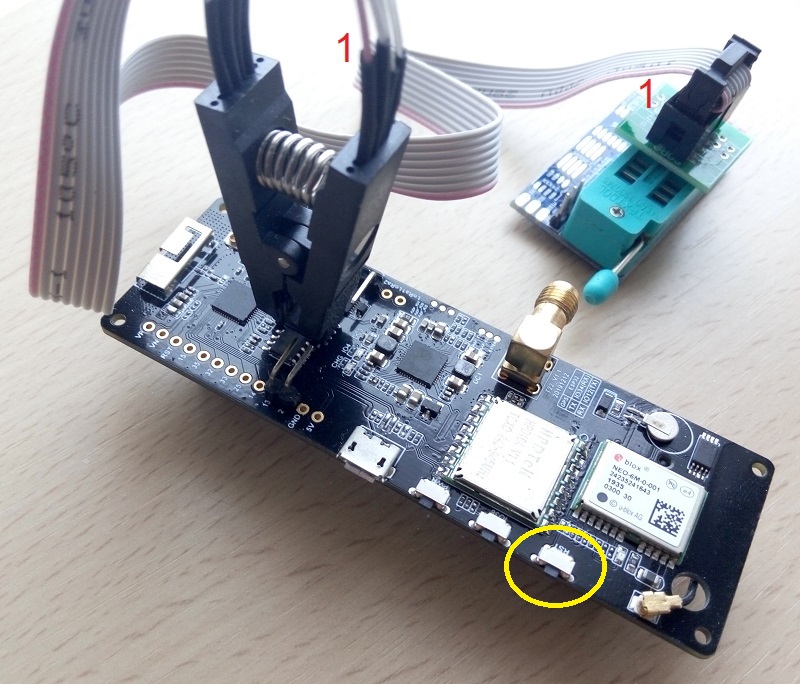
“Brute force” method of installing/updating TTGO T-Beam firmware is explained there.
This low cost (3-4USD) method can help when a particular board has microUSB (D+/D-) and/or ESP32 GPIO0 related issues.
3 Likes
I has a small year ago TTN mapper working on my t-beam. It works ok. But Now i can’t get it working anymore. In Arduino i got message like:
C:\Users\Gebruiker\Documents\Arduino\libraries\MCCI_LoRaWAN_LMIC_library\src\hal\getpinmap_thisboard.cpp: In function 'const Arduino_LMIC::HalPinmap_t* Arduino_LMIC::GetPinmap_ThisBoard()':
C:\Users\Gebruiker\Documents\Arduino\libraries\MCCI_LoRaWAN_LMIC_library\src\hal\getpinmap_thisboard.cpp:69:72: note: #pragma message: Board not supported -- use an explicit pinmap
     #pragma message("Board not supported -- use an explicit pinmap")
                                                                    ^
And in Platformio is totally difficult. I should set in ''project confg" of the library the correct frequency but if i do i got a lot of errors because you need to configure the frequency just one time. What i did i changed only US915 in EU868 as described on step 3 of the TTN Mapper.
So i think the ttn mapper does not work anymore. Is there not somewhere a simple .bin file?
I got that pinmatic and board not supported by every lora application…
1 Like
@ haajee There are many TTN mapper projects. Can you provide a link to the project you tried?
In my experience it is mandatory to use the exact LMIC referenced in the original project. As long as possible in the exact version originally used.
1 Like
FYI, see:
The axp.setDCDC1Voltage(3300) fixed it.
2 Likes
<rant-mode>
Continuing my rant from Big ESP32 + SX127x topic part 3 - #396 by bluejedi :
-
In TTGO T-Beam V1.0 and V1.1 circuit diagrams all button switches are labeled “reset”!
-
Since 2020 Q4 The TTGO T-Beam (V1.1) is available in two very different configurations:
-
With SX127x LoRa module
This uses the original SX127x LoRa chip.
This will work with the MCCI LMIC LoRaWAN library. -
With SX1262 LoRa module
This uses the newer SX1262 LoRa chip.
This will NOT work with the MCCI LMIC LoRaWAN library
and requires a different LoRaWAN library with SX1262 support!
(MCCI LMIC currently does not support SX1262.)In all their ‘wisdom’ LilyGO decided to use the same name for both models:
TTGO T-Tbeam V1.1 (a.k.a. T22 V1.1).
So just the name and version are not enough to know anymore.
You will now in addition also need to know which of these different LoRa modules is mounted on the board. The only way to see the difference is the text “SX1262” on the label on the LoRa module. And don’t forget that there are also different versions for different regions (ISM band frequencies).
-
</rant-mode>
Below is a correct overview of the button names and their function and how each is powered:
| Button switch name | Function | Powered by |
|---|---|---|
| SW4 | Reset | +3.3V |
| SW5 | User button, GPIO38 (active-low) | +3.3V |
| SW6 | Power | VSys |
Note my post above about the +3.3V line. It needs to be programmed/configured correctly before the +3.3V line will actually carry 3.3V. If the voltage is too low this may impact (prevent) proper operation of the board and the buttons powered via +3.3V.
3 Likes
Hey guys! First post here, looking for some help.
I’ve successfully connected my TTGO T-Beam to my TTN account. The payload decoder script at TTN keeps showing unrealistic values even though I’m getting this right at my board.
Here’s my buildPacket function that runs inside my TTGO
And this is what I get to see at my Serial Monitor
This is the payload that I got from this message
And this is the Decoder Function that I pushed to TTN
And finally this is what I got when TTN decodes my payload
1 Like
You can’t do what you think you can do with floats so easily - you haven’t told JavaScript you are actually reassembly a float so it just looks like a long integer to it.
Much simpler to multiply up the float to get the precision you need, like 1000, turn it in to a integer, then split it in two, send it, put it back to one and then divide by 1000.
2 Likes
I’m having the same issue. With this repo:
https://github.com/hottimuc/Lora-TTNMapper-T-Beam
How did you solve the problem?
1 Like
I’ve found a solution for
GitHub - hottimuc/Lora-TTNMapper-T-Beam: TTNMapper on the TTGO T-Beam
and TTN - OTAA
Modifications needed:
void loop() {
  if(LoraStatus == "EV_JOINING"){
    os_runloop_once();
  }
 // AXP powermanagement IRQ-handling
 if (axpIrq) {
      Serial.println("AXP IRQ!");
      axpIrq = 0;
     axp.readIRQ();
     if (axp.isPEKLongtPressIRQ()) {
    ...
and
void do_send(osjob_t* j) {

  if(LoraStatus == "EV_JOINING"){
    Serial.println(F("Not joined yet"));
    // Check if there is not a current TX/RX job running
    os_setTimedCallback(&sendjob, os_getTime() + sec2osticks(TX_INTERVAL), do_send);
  } else if (LMIC.opmode & OP_TXRXPEND)
  {
    Serial.println(F("OP_TXRXPEND, not sending"));
    LoraStatus = "OP_TXRXPEND, not sending";
  }
  else
  {
    if (gps.checkGpsFix())
    {
      // Prepare upstream data transmission at the next possible time.
      gps.buildPacket(txBuffer);
      LMIC_setTxData2(port, txBuffer, sizeof(txBuffer), 0);
      Serial.println(F("Packet queued"));
      axp.setChgLEDMode(ledMode);
      LoraStatus = "Packet queued";
    } else {
      //try again in 3 seconds
      os_setTimedCallback(&sendjob, os_getTime() + sec2osticks(3), do_send);
    }
  }
  // Next TX is scheduled after TX_COMPLETE event.
}
1 Like
Thanks for the code! Any ideas for the following error I get after the code upload?
17:59:20.169 → TTN Mapper
17:59:20.169 → FAILURE
17:59:20.169 → C:\Users\jbejarano\Documents\Arduino\libraries\IBM_LMIC_framework\src\lmic\radio.c:689
Thanks in advanved!!
1 Like
Most likely an unexpected radio id compared to the settings in the config.
Which exact (ie where did you get it from on the internet) and version of the LMiC library are you using?
1 Like
I got it from Arduino manager. (here is the screenshot 05.06.2021-08.00.58): IBM LMIC Framework. I tried first with latest version (1.5.1) and then -due the error- I switched to 1.5.0 arduino-1.
Below an part of config.h (lmic library… these lines were modified)
//#define CFG_eu868 1
#define CFG_us915 1
// This is the SX1272/SX1273 radio, which is also used on the HopeRF
// RFM92 boards.
//#define CFG_sx1272_radio 1
// This is the SX1276/SX1277/SX1278/SX1279 radio, which is also used on
// the HopeRF RFM95 boards.
#define CFG_sx1276_radio 1
Thanks for the help!
1 Like
There is a newer TTGO T-Beam v1.1 in the market, which is sold with either SX1276 (or compatible HOPE chip) or SX1262.
LMIC radio controller currently has no support for SX1262. Thus, check your device for Lora chip type. So far there is no chance to get LMIC working on SX1262, unless someone implements this in LMIC.
1 Like
Thanks for the help. I am sorry, did not catch your answer before. I finally make it work. There was a pin id issue with my code. I appreciate your time on this.
1 Like